background image

Zimmer GmbH 

 Im Salmenkopf 5 

 77866 Rheinau, Germany 

 Phone: +49 7844 9138-0 

●  

Fax: +49 7844 9138-80 

 www.zimmer-group.de

DDOC00198/t

EN/2015-10-07

15

INSTALLATION AND OPERATING INSTRUCTIONS: 

ELECTRIC GRIPPER GEP/GED5000 SERIES

9. Maintenance

9.1 

Maintenance intervals

The gripper does not require maintenance. 

The operational life of up to 30 million cycles may become reduced under the following circumstances:


• Dirty environment


• Improper use


• Unapproved performance data and parameters for use


• Use of sealing air

9.2 

Disassembling the gripper

We recommend using the Zimmer Group Repair Service for repairs. 

Unauthorized dismantling and reassembly of the gripper can result in complications as in some cases, special mounting equipment 

is required. In addition, the warranty is void if the gripper is opened.

10. Remedy

10.1 

Error diagnosis

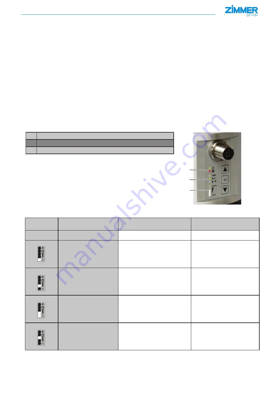
The red error LED indicates that an error has occurred. The main menu must be selected to see the error code. The five lower LEDs 

represent the current error code in binary form. 

In the following example, 

error code 7

 is active:

The error is acknowledged via a new DIR signal.

1

2

3

1

"Error" LED display

2

Position display

3

Error code display

10.2 

Display troubleshooting

Error code

Error

Possible cause

Measure

0

No error

1

Motor has slight overcurrent in 

several consecutively following 

cycles

•  Gripper is difficult to move

•  Travel path of the gripper is 

impeded

•  Object being gripped or gripper 

jaws are elastic

•  Check the gripper's freedom of 

movement

•  Check the object being gripped 

and gripper jaws

2

Motor has strong excess 

current

•  Gripper is blocked

•  Internal error

•  Restore the free movement of the 

gripper once again

•  

 Zimmer Group Service

3

Motor has excess current in 

idle mode

•  Internal error

•  

 Zimmer Group Service

4

Motor output stage 

temperature above the limit 

value

•  Ambient temperature too high

•  Gripper is overloaded

•  Provide sufficient ventilation/

cooling

•  Check the object to be gripped or 

the gripper jaw

*) See "Glossary" section for definitions

Содержание GED5000 Series

Страница 1: ...INSTALLATION AND OPERATING INSTRUCTIONS Handling Technology GEP GED5000 series Electric gripper THE KNOW HOW FACTORY ...

Страница 2: ...caused by improper use 2 Proper use The gripper is designed exclusively for electric operation using a supply voltage of 24 V DC The gripper is used as defined under Proper use in enclosed rooms to temporarily grip handle and hold parts The gripper is not suitable for clamping workpieces during a machining process Direct contact with perishable goods food is not permitted 3 PNP switching logic use...

Страница 3: ...oves at high speed back into the starting position The gripper is suitable for inward gripping NC normaly closed This means the gripper moves at high speed back into the starting position NC NO 4 1 GEP5000 function NC NO 4 2 GED5000 function The gripper fingers of the three jaw gripper are each positioned between two steel guide rails A brushless DC motor is used as the drive The rotational moveme...

Страница 4: ...be carried out to install the gripper Insert centering sleeves into the provided matching parts on the gripper Position the gripper on the designated mounting surface using the centering sleeves Secure the gripper with cylinder screws of strength class 8 8 Install the KAG1000B8 power supply cable straight plug or the KAW1000B8 power supply cable angled plug NOTE Non compliance may result in damage...

Страница 5: ...ion the energy consumption of the gripper is 150 mA The parameters can be set using the arrow keys on the membrane keyboard see section 7 3 Pin Color Function Explanation 1 White DIR INPUT open close gripper control input 24 V DC 2 Brown Work position OUTPUT gripper in work position message 3 Green Error OUTPUT error message 4 Yellow Teach position OUTPUT gripper in programming position message 5 ...

Страница 6: ...own on the gripper via the LED display See Glossary section for definitions Course of action for teaching the gripper with workpiece Put the gripper jaws into the desired position for instance by inserting a workpiece Close the gripper by applying a signal 24V at the PIN 1 arrow 1 input Error display lights up red arrow A Apply a signal 24 V arrow 2 on the pin 7 input teach adjust for 0 5 to 3 sec...

Страница 7: ...raversing routine the procedure must be repeated because the end positions are not correctly determined 7 5 Minimum travel path The gripper requires a minimum travel path of 1 25 mm per jaw before it is permitted to reach a workpiece Failure to do so means the gripper cannot establish the desired gripping force and displays an error The minimum travel path applies to both movement directions and i...

Страница 8: ...ue Changing the value Changing the value Changing the value Call up the main menu by pressing SET 3 seconds The menu display LEDs will flash You can access the edit mode of a value by pressing SET once again Parameter display LEDs will flash Only possible in menus that feature a selection point A value can be changed in a range from 1 to 5 using the arrow keys Pressing SET saves the value and goes...

Страница 9: ...cycle time 3 NO operation outward gripping with the desired force mode quick inward movement for reducing the cycle time Default value 1 If the gripping direction is defined the corresponding gripper mode 2 or 3 shall be used The entire gripping cycle is sped up on the basis of the shorter return time of the gripper jaws As a result the gripper is operated mechanically and electrically milder to e...

Страница 10: ...ease contact ZIMMER GmbH Customer Service For this purpose please call our technology hotline at 49 7844 9138 0 8 6 2 Menu 2 Width teach area GEP5006 GED5006 Teach area Width mm Teach area width 1 0 2 mm Teach area width 2 0 4 mm Teach area width 3 0 6 mm Teach area width 4 1 2 mm Teach area width 5 2 4 mm GEP5010 GED5010 Teach area Width mm Teach area width 1 0 2 mm Teach area width 2 0 4 mm Teac...

Страница 11: ...ing mode GEP5006 GED5006 Force setting Value 1 Value 2 Value 3 Value 4 Value 5 Gripping force during closing N 540 620 710 860 960 Gripping force during opening N Travel time during closing s 0 22 0 2 0 18 0 16 0 15 Travel time during opening s 0 13 0 13 0 13 0 13 0 13 Effective closing time s 0 255 0 235 0 215 0 195 0 165 Effective opening time s 0 165 0 165 0 165 0 165 0 165 Max length of grippe...

Страница 12: ...08 GED5008 Force setting Value 1 Value 2 Value 3 Value 4 Value 5 Gripping force during closing N 650 790 920 1090 1150 Gripping force during opening N Travel time during closing s 0 29 0 27 0 25 0 22 0 18 Travel time during opening s 0 15 0 15 0 15 0 15 0 15 Effective closing time s 0 335 0 305 0 285 0 255 0 215 Effective opening time s 0 185 0 185 0 185 0 185 0 185 Max length of gripper jaws mm 1...

Страница 13: ...mode GEP5010 GED5010 Force setting Value 1 Value 2 Value 3 Value 4 Value 5 Gripping force during closing N 980 1080 1200 1400 1520 Gripping force during opening N Travel time during closing s 0 32 0 29 0 27 0 24 0 21 Travel time during opening s 0 16 0 16 0 16 0 16 0 16 Effective closing time s 0 345 0 325 0 295 0 275 0 245 Effective opening time s 0 2 0 2 0 2 0 2 0 2 Max length of gripper jaws mm...

Страница 14: ...mm Teach area offset 1 0 8 mm Teach area offset 2 0 4 mm Teach area offset 3 0 mm Teach area offset 4 0 4 mm Teach area offset 5 0 8 mm GEP5010 GED5010 Position teach area Offset mm Teach area offset 1 0 8 mm Teach area offset 2 0 4 mm Teach area offset 3 0 mm Teach area offset 4 0 4 mm Teach area offset 5 0 8 mm GEP5008 GED5008 Position teach area Offset mm Teach area offset 1 0 8 mm Teach area o...

Страница 15: ...ain menu must be selected to see the error code The five lower LEDs represent the current error code in binary form In the following example error code 7 is active The error is acknowledged via a new DIR signal 1 2 3 1 Error LED display 2 Position display 3 Error code display 10 2 Display troubleshooting Error code Error Possible cause Measure 0 No error 1 Motor has slight overcurrent in several c...

Страница 16: ...ts work base or teach in position Check the object being gripped or the gripper jaws 9 Gripper does not reach the target speed Difficulty moving the guide Zimmer Group Service 10 The jaw position sensor has an error Internal error Zimmer Group Service 11 The temperature sensor has an error Internal error Zimmer Group Service 12 The gripper has a general system error Internal error Zimmer Group Ser...

Страница 17: ... the target speed when approaching Difficulty moving the guide Zimmer Group Service 18 Gripper is in NC or NO mode and is blocked from free run see Section 7 5 menu 3 menu function Gripper is difficult to move In its fast backward movement the gripper moves to a fixed stop i e object being gripped Change gripper mode Zimmer Group Service INFORMATION Important for handling the product Errors remain...

Страница 18: ...nding signature Managing Partner 11 Declaration of Incorporation in the context of EU Machinery Directive 2006 42 EC Annex II 1 B Name and address of the manufacturer ZIMMER GmbH Im Salmenkopf 5 D 77866 Rheinau Germany Phone 49 7844 91380 www zimmer group de We hereby declare that the incomplete machines described below Product designation Electric parallel gripper electric three jaw gripper Type ...

Страница 19: ...on Base position of the gripper DC motor Motor run on DC power DIR Direction 24 V supply line Error Fault error message ESD Electrostatic discharge electrostatic sensitivity GED Gripper electrically powered three jaw design GEP Gripper electrically powered 2 parallel jaws GND Abbreviation for Ground ground connection LED Light emitting diode NO Normally Open gripper mode inward gripping the grippe...

Отзывы: