SSG-0101 ZetaAlarm Systems
6
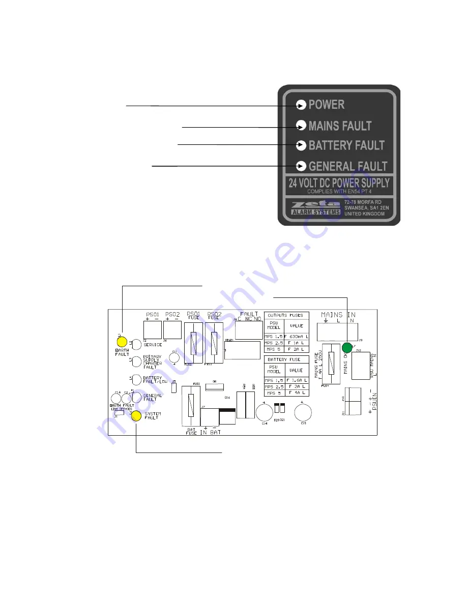
FRONT
PANEL:
2. LED DESCRIPTION AND OPERATION
INTERNAL LEDS:
GENERAL FAULT
SERVICE
PRIMARY POWER SUPPLY FAULT /
BATTERY CHARGER FAULT
BATTERIES NOT CONNECTED FAULT /
LOW BATTERY WARNING
EARTH SHUNT
SYSTEM FAULT
MAINS PRESENCE


