SIMPLICITY PLUS INSTALLATION MANUAL
Approved Document No: GLT.MAN-107
PAGE 41
Issue 3.16 Author: NRPJ Date: 21/09/2017
Earth fault (Earth fault is generally disabled on the PSU because the earth fault is monitored by panel)
19.5 EARTH FAULTS
An EARTH fault indicates that something is shorting to earth (usually through the cable screen).
Disconnect the earth screens one at a time to determine the problem line.
(Note: connecting other equipment , e.g. an oscilloscope or a PC , to the panel can give an
earth fault)
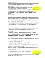
*** FAULT ***
1 of 1
Earth Fault Pos
The Screen will indicate if it is a Positive or Negative voltage shorting to earth (Earth Fault Pos or Earth Fault Neg).
***DO NOT DISCONNECT THE MAINS EARTH CONNECTION. THIS WILL CAUSE A PROBLEM WITH THE PANELS
OPERATION***
19.6 DOUBLE ADDRESS
This indicates that a double address has been detected. This usually happens during initial setup, where 2 detectors are
given the same address, or if a head is replaced during maintenance, and its address has been wrongly set. In the second
scenario, the panel will report 2 fault addresses, one will be the double address, and the other will be a missing device. As
a further aid to finding the fault, the panel will light the LEDs of any detectors with a double address (Sounders & I/O units
will not be indicated as they have no panel controlled LED to light up)
Make a list of the double addresses reported (there may be more than one).
Go to view device screen in Configuration menu 1. Scroll through the devices, and make a list of any that are missing
(Note: the panel skips over empty addresses when scrolling)
Go to the location of the missing device, and check if it has its LED on (Detector), or check the dip switch setting.
If this does not cure all double addresses, go to the known location, and temporarily remove the device. The panel will
now report the type of device that was also configured to this address from the view device screen. This will help narrow
down the search for the device. (e.g. if extra device is call point, check the address settings of all the call points)
19.7 SYSTEM FAULT
A system fault is an abnormal microprocessor running condition due to various unexpected phenomena.
This will result in the panel attempting to correct itself. Should this fault occur, the System Fault LED, General Fault LED,
General Fault relay and fault internal buzzer will be constantly active until the control keyswitch is turned from off position
to control enable position. This should cause this fault condition to reset. If not, consult your supplier.
19.8 PRE-ALARM
This is not a fault condition. The panel has detected a high reading from one of the devices on the loop. This could be
caused by a fire starting (in which case it acts as an early warning), or it could be caused by a contaminated head. The
panel will report the location of the problem device, which should then be investigated.
The PRE-ALM LED is illuminated constantly during the pre-alarm condition.
Note that the same LED is used during the
confirmation period of Alarm Verification (see section 13), but in this case the LED flashes.
19.9 SOUNDER FAULTS
On the Simplicity there are only loop controlled sounders, but there may be conventional sounder circuits connected via a
ZSCC - Sounder circuit controllers (ZSCC).
Check that the correct END of Line resistor is fitted. (47K – Yellow, purple, orange, gold)
Check that the sounder fuses is OK (FS1, – 4000mA TD)
If working on an existing installation, check that the devices are polarised. (See Page 5)
Check cable continuity (remove from panel and measure continuity. Should read 47K)
Check its external power supply is connected & working
For loop powered sounders, check that all sounders are communicating, and check their analogue value. If a sounder is
returning a value less than 8, then it has detected an internal fault and should be replaced.
If they are not communicating, then check that they have power, and that the power is connected the correct way. If they
have power, they may be damaged. Try a replacement if available.
Note that common sounder bases, and associated sounders are only monitored through the cable continuity (similar to a
conventional sounder circuit), so are not able to give any fault messages.
19.10 LOOP WIRING FAULTS
A loop fault can be caused by a break, or short circuit in the Loop wiring. Open the panel and
look for the 2 LOOP ON LEDs on the termination PCB. (4 LEDs for a 2 loop Simplicity).Under
normal conditions these should be all lit steady. The LEDs represent Loop1 Side A and Loop 1
*** FAULT ***
1 of 1
Loop 1 Cable Fault


