background image


ZoningBOX 6 / ZoningBOX 4


http://www.zennio.com


Technical Support:


http://support.zennio.com


17 

2.2.3


MODE 

Each  HVAC  unit  works  necessarily  under  one  of  the  following  operation  modes  at  a 

time, which therefore is applied to all zones included in its group: 


Heating

:  the  unit  will  generate  hot  air  to  warm  the  zones.  The  grille  control 

will  be  intended  to  make  the  local  reference  temperature  reach  the  zone 

setpoint temperature. 


Cooling

:  the  unit  will  generate  cold  air  to  refrigerate  the  zones.  The  grille 

control will be intended to make the local reference temperature fall under the 

zone setpoint temperature. 


Fan

: the unit will generate an air flow at the ambient temperature. The grilles 

of the enabled zones will remain open. 


Dry

: the unit will generate a dry air flow to reduce the  ambient humidity. The 

grilles of the enabled zones will remain open as in Fan mode. 

The  operation  mode  of  the  HVAC  unit  will  depend  on  the  user  needs.  Therefore, 

ZoningBOX incorporates specific 

input objects

 for each group of zones, which can be 

linked to the above elements. It also incorporates 

output objects

 (status objects) to be 

linked with the gateways of the HVAC units, so whenever ZoningBOX receives a mode 

change order, it can be forwarded to the corresponding HVAC unit.  

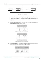
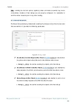
The following diagram illustrates this configuration. 


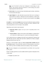
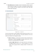
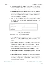
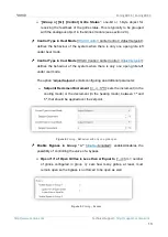
The involved mode selection objects can be of different types: 


Individual  control  (one  bit)

:


one  binary  object  is  provided  per  mode, 

together with their corresponding status objects. 

Controller / 

Thermostat 

from Zone “x” 

Zoning 

Module 

HVAC Unit 

Gateway 

Mode 

Mode (Status) 

Figure 15. 

Mode control


Содержание ZCL-ZB4

Страница 1: ...ZoningBOX 6 ZoningBOX 4 Ducted Air Zoning Actuator for 6 4 Zones ZCL ZB6 ZCL ZB4 USER MANUAL Application program version 2 1 User manual edition 2 1 _a www zennio com...

Страница 2: ...n 5 1 3 Start Up and Power Loss 6 2 Configuration 7 2 1 General 7 2 2 Zones 9 2 2 1 Configuration 9 2 2 2 Grille Control 16 2 2 3 Mode 17 2 2 4 Fan 19 2 2 5 Temperature Setpoint 24 2 2 6 Scenes 27 2 2...

Страница 3: ...anges in the application program New parameter for advanced current control 32 2 0 _a Changes in the application program New operating mode positional control Optimisation of the global setpoint tempe...

Страница 4: ...f up to six or four zones Manual control over the different grilles through the on board push buttons LED indication of the output channels status and for error notification Zoning module responsible...

Страница 5: ...the KNX bus the device will enter into safe mode In such case the LED will blink in red every 0 5 seconds Output channels 5 output ports for the insertion of the stripped cables of the grilles being...

Страница 6: ...ennio com 1 3 START UP AND POWER LOSS Depending on the configuration some specific actions may be performed during the device start up For example the integrator can set whether the grilles should swi...

Страница 7: ...ase for practical purposes please consider them as a sole grille This document and its figures are generally referred to ZoningBOX 6 However note that all functions are entirely analogous in ZoningBOX...

Страница 8: ...ts Reset 0 and Reset 1 which will be sent to the KNX bus with values 0 and 1 respectively whenever the device begins operation for example after a bus power failure It is possible to parameterise a ce...

Страница 9: ...ure i e the current temperature in the room Control signal from the thermostat One communication object is provided for the reception of each of the above values being it possible to link these object...

Страница 10: ...rilles are to be forced open is also possible Depending on which control mode is selected Open Close Mode bypass can only be set if it physically exists in the installation Positional Mode bypass can...

Страница 11: ...the zoning module has been activated in the General tab see section 2 1 the tab tree will show a new entry named Zones The general parameters of the zone control are contained in the Configuration win...
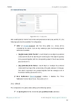
Страница 12: ...igure 7 Zoning Zone Configuration The following objects are provided for each zone Group n Zi Disable Enable Zone one bit object for the reception of the requests to enable or disable the zone from a...

Страница 13: ...point defines the behaviour of the system when there is only one open grille left under cool mode The option Adjust Setpoint entails configuring an additional parameter Setpoint Decrement Increment 1...

Страница 14: ...perational bypass mode when positional mode is enabled When Damper mode is selected the Desired Position 0 100 parameter will be displayed It defines which position the bypass will take when the open...

Страница 15: ...time delay prior to closing the last grille or the bypass after switching off the HVAC unit Delay to Turn On HVAC Unit 0 1 255 s sets a time delay before the HVAC unit can be switched back on in case...

Страница 16: ...der received with a value between 0 and Intermediate Control Point 1 will implies an opening value of Grille Position 1 0 20 100 Intermediate Control Point 2 0 75 100 sets a limit so every order recei...

Страница 17: ...ed zones will remain open Dry the unit will generate a dry air flow to reduce the ambient humidity The grilles of the enabled zones will remain open as in Fan mode The operation mode of the HVAC unit...

Страница 18: ...ers between Cooling value 0 and Heating value 1 In case the Fan and Dry modes are activated through the above controls the status object of this one will show the value 0 Every time a mode switchover...

Страница 19: ...ber of in demand zones and a ponderation factor for each zone Manual control the user can directly take part in the selection of the desired speed through a set of communication objects of different t...

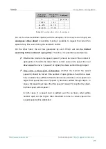
Страница 20: ...proper integer value 1 2 3 Object Value Fan Speed 0 Ignore order 1 1 2 2 2 Ignore order Table 2 Enumerate control for two speeds Object Vale Fan Speed 0 Ignore order 1 1 2 2 3 3 3 Ignore order Table...

Страница 21: ...meterise Whether the minimum fan speed speed 1 should be forced if the number of open grilles is found to be lower than a certain value and a speed fan level above speed fan level 1 speed 2 or higher...

Страница 22: ...object for each fan speed level available in each HVAC unit either two or three see below Two speeds Unit x Fan Speed Minimum and Unit x Fan Speed Maximum Three speeds as above plus Unit i Fan Speed...

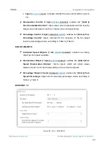
Страница 23: ...an Percentage Control object intended for the reception of the fan speed levels as percentage values according to Table 4 y Table 5 STATUS OBJECTS Individual Speed Objects 1 bit disabled enabled enabl...

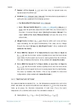
Страница 24: ...ic fan mode Force MIN Fan Speed if n of Open Grilles is Less than or Equal to 0 1 12 sets the minimum number of grilles minus one that must remain open before the fan speed can be set to levels greate...

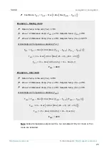
Страница 25: ...EF2 20 C Setpoint Temp TLSP2 26 5 C Global Setpoint Temperature calculate TGSP 0 1 1 2 2 19 0 25 21 26 5 20 19 0 6 5 19 0 7 Example 2 Cool mode Return Temp to the unit TRET 26 C Zone 1 Reference Temp...

Страница 26: ...ess consists in truncating TGSP to comply with this parameterisation An object is available to disable or re enable this functionality dynamically as well as two more objects to modify the limits orig...

Страница 27: ...2 5 sets the value of the increment in the heating mode or the decrement in the cooling mode to be applied over the global setpoint The global setpoint temperature is calculated from the value assigne...

Страница 28: ...ene n up to six Scene number 1 64 value that will trigger the execution of the scene if received through the Scenes object Group of Zones 1 2 zone group 1 or 2 if two groups have been parameterised se...

Страница 29: ...Mode Status Unit x Heat Mode Status Unit x Cool Mode Status Unit x Fan Mode Status Unit x Dry Mode Status Unit x Simplified Mode Status Unit x Fan Speed Percentage Status Unit x Fan Speed Enumeration...

Страница 30: ...owing parameters Figure 23 Zoning Reset Send Grilles Control Objects After Reset disabled enabled sets whether the grille control objects should be sent to the KNX bus after a reset Delay 0 255 s time...

Страница 31: ...e they will be also jointly controllable by the same output as long as they are the same model There are two control modes depending on operation mode enabled see section 2 1 for more details When Ope...

Страница 32: ...positional control which should be sent the grill control signal This object is typically to be grouped together with the corresponding object of the Zones module see section 2 2 1 Gy Actuator Grille...

Страница 33: ...the grill movement end Important Its use is not recommended except for exceptional cases where advanced control of the ZoningBOX is necessary ETS PARAMETERISATION Once a specific grille has been enab...

Страница 34: ...cessary 2 3 3 ERROR NOTIFICATION Enabling the error notification function allows ZoningBOX to report certain error events through the KNX bus Connection error it will be reported when either an open c...

Страница 35: ...bout errors via the available LEDs on each output if any of the following errors have occurred power supply failure connection error short circuit and open circuit error overload error ERROR LEDS DESC...

Страница 36: ...s the overload error objects Gy Overload Error one per grille which are sent with value 1 as soon as the overload error is detected in the corresponding grille and with value 0 when the error is over...

Страница 37: ...ce this situation is over The error objects are sent periodically every thirty seconds while their value is 1 However once they adopt the value 0 they are only sent once Note leaving these checkboxes...

Страница 38: ...released which means the device has left the Test On mode Note that it will also leave this mode if a bus power failure takes place Once in the Test On mode any orders from the KNX that may affect th...

Страница 39: ...parameterised Manual Control Lock disabled enabled provides an optional procedure for locking the manual control in runtime When this checkbox is enabled object Manual Control Lock turns visible as w...

Страница 40: ...e Group n Zi Setpoint Temperature Group n Zi Reference Temperature Group n Zi Control Signal from Thermostat Unit x Mode status Unit x Global Temperature Setpoint Unit x Fan Speed status Unit x Open C...

Страница 41: ...nt Temperature 6 10 14 18 22 26 30 34 38 42 46 50 2 Bytes I C W T U DPT_Value_Temp 273 00 670433 28 Group x Zx Reference Temperature Reference Temperature 7 11 15 19 23 27 31 35 39 43 47 51 1 Bit I C...

Страница 42: ...C W T U DPT_Value_Temp 273 00 670433 28 Unit x Maximum Heat Mode Maximum in Range 106 139 2 Bytes I C W T U DPT_Value_Temp 273 00 670433 28 Unit x Return Temperature Return Temp from External Sensor 1...

Страница 43: ...64 167 172 177 182 187 192 1 Bit I C W DPT_OpenClose 0 1 Gx Actuator Grille Position 0 Open 1 Close 1 Byte I C W DPT_Scaling 0 100 Gx Actuator Grille Position 0 100 168 173 178 183 188 193 1 Bit O C...

Страница 44: ...n and send us your inquiries about Zennio devices http support zennio com Zennio Avance y Tecnolog a S L C R o Jarama 132 Nave P 8 11 45007 Toledo Spain Tel 34 925 232 002 www zennio com info zennio c...

Отзывы: