

MINiBOX 0-10V X3/X2/X1
Technical Support:
5
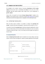
1.2
INSTALLATION
The MINiBOX 0-10V devices connect to the KNX bus through the on-board KNX
connector. Once the device is provided with power from the KNX bus, both the individual
address and the associated application program may be downloaded.
This device does not need any additional external power since it is entirely powered
through the KNX bus.
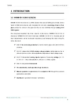
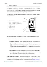
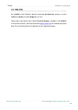
Figure 1.
MINiBOX 0-10V X3. Elements
Note:
the previous figure is analogous for MINiBOX 0-10V X2 and MINiBOX 0-10V X1
The main elements of the device are described next.
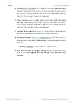
Test/Prog. Button (4)
: a short press on this button sets the device into the
programming mode, making the associated
LED (5)
light in red.
Note
:
if this button is held while plugging the device into the KNX bus, the
device will enter into safe mode. In such case, the LED will blink in red every
0.5 seconds.
Inputs/Outputs (1)
: inputs/output ports for the insertion of the stripped cables
of the systems being controlled by the actuator (see sections 2.2 and 2.3).
Please secure the connection by means of the on-board screws.
To get detailed information about the technical features of this device, as well as on the
installation and security procedures, please refer to the corresponding
Datasheet
,
bundled with the original package of the device and also available at
1.
Inputs/Outputs.
2.
0-10V Output LED Indicator.
3.
0-10V Output Manual Control Button
4.
Prog./Test Button.
5.
Prog./Test LED.
6.
KNX Connector.
7.
Fixing Clamp.
1
5
3
4
6
2
7


