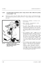
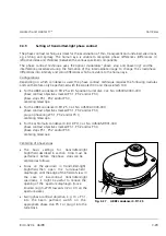


Carl Zeiss
Axiotech and Axiotech
vario
3-42
B 40-020 e 06/99
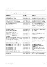
•
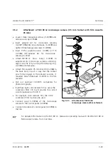
zero reset of the digital display at any point of the "0" measuring range, e.g. at the starting or end
point of the measured distance,
•
measuring unit of the display in inch or mm "IN/M" with 1 inch = 25.4 mm.
Furthermore, the
RS 232 C
data output
is available, which allows a printer and a computer to be
connected for measurement logs and measured value processing via the 16 Eiv interface.
For further information, please see the enclosed manual "Digital Micrometer 46 EH".
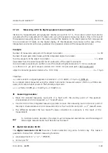
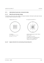
3.7.3
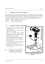
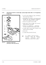
Determination of microhardness using the MHT-4 microhardness tester
The MHT-4 microhardness tester is used to determine the microhardness applying loads ranging from
0.0005 to 2 N (i.e. 0.05 to 200 p):
The microhardness tester consists of:
−
MHT-4 sensor and
−
MHT-4 control unit
The sensor is screwed into the objective nosepiece via its W 0.8
×
1/36“ thread. In nosepieces with M 27
×
0.75 thread, it can be attached via an intermediate ring. The sensors can be equipped with either
VICKERS
or
KNOOP
diamonds.
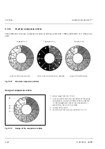
All the parameters and functions for microhardness determination are entered via the keyboard of the
control unit and are shown alphanumerically on a LC display.
The measurement itself is shown on the video monitor. A digitizing instrument (mouse) is used to move
lines visible on the monitor to the ends of the diagonal of indentation, like a micrometer, and the length
of these lines can then be read.
The RS-232-C serial interface allows the connection of a printer for the recording of all parameters which
have been entered, measured and calculated.
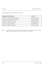
For further information on the use of the MHT-4 microhardness tester, please see brochure GK 42-170.
Содержание Axiotech
Страница 1: ...Axiotech and Axiotechvario Materials Microscopes Operating Manual...
Страница 14: ...Carl Zeiss Axiotech and Axiotechvario XIV B 40 020 e 06 99...
Страница 16: ...Carl Zeiss Axiotech and Axiotechvario 1 2 B 40 020 e 06 99...
Страница 20: ...Carl Zeiss Axiotech and Axiotechvario 1 6 B 40 020 e 06 99 Fig 1 2 Microscope components and modules sheet 2...
Страница 112: ...Carl Zeiss Axiotech and Axiotechvario 3 46 B 40 020 e 06 99...
Страница 114: ...Carl Zeiss Axiotech and Axiotechvario 4 2 B 40 020 e 06 99...
Страница 124: ...Carl Zeiss Axiotech and Axiotechvario A 2 B 40 020 e 06 99...


