Zehnder Rittling ComfoAir 200 Скачать руководство пользователя страница 44

3

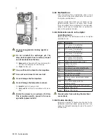
EN - 40 - For the installer

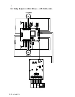
3.14  Wiring diagram: ComfoAir 200 Luxe  – LEFT-HAND version

J1

RS485
Entalpy

RS485
Hybalans

RS232
KFB

12V

0-10V

A1

A2

GND

12V

B

A

GND

12V

B

A

GND

12V

RX

TX

GND

RS232
PC

PCB
Hybalans

0-10V

M

M

RS232

Black

Red

White

Brown

M

White

Brown

Blue (-)

Y

e

llow (0-10V)

White   (         )

M

DISPLA

Y

Bathroom switch (volt free contact)

Pre-heater

T1

T4

T3

T2

Bypass valve

Green/ Y

e

llow

Brown

Blue

Blue

Brown

Red

Black

White

Brown

White

Brown

White  (         )

Y

e

llow  (0-10V)

Blue(-)

(L3) Brown

(N) Blue

SUPPLY

EXHAUST

RJ45

VENT.

VENT

.

FIL

T2/T4

T1/T3

BYP/PIE

TRI

VENT.

BS

VENT

.

1

T2/T4

T1/T3

BYP/PIE

-

+

Green/ Y

e

llow

Green/ Y

e

llow

Pre-heater valve

Содержание ComfoAir 200

Страница 1: ...ComfoAir 200 Manual...

Страница 2: ...EN II All rights reserved This manual has been compiled with the utmost care The publisher cannot be held liable for any damage caused as a result of missing or incorrect information in this manual...

Страница 3: ...8 Pre heater optional 4 2 1 9 Enthalpy optional 4 2 2 Available operating devices 4 2 2 1 Display 4 2 2 2 3 position switch 5 2 2 3 CO2 sensor 5 2 2 4 Bathroom switch 5 2 2 5 CC Ease panel 5 2 3 Oper...

Страница 4: ...ucts 22 3 6 4 Connection of the condensation drain 22 3 7 Commissioning the ComfoAir 23 3 7 1 Display on the unit 23 3 7 2 CC Ease panel 24 3 7 3 P menus for the installer 26 3 8 Programming air speci...

Страница 5: ...oAir is covered by a manufacturer s war ranty for a period of 24 months after fitting up to a maximum of 30 months after the date of manufac ture Warranty claims may only be submitted for ma terial fa...

Страница 6: ...d instructions as prescribed in this man ual at all times Keep this manual with the ComfoAir throughout its life Instructions with regard to cleaning or replacing the filters of the intake and exhaust...

Страница 7: ...ss works automatically All you have to do is set the required comfort tem perature 2 1 4 Frost protection The ComfoAir is also fitted with a frost protection de vice This is an automatic protective sy...

Страница 8: ...nit select menu up OK down supply off supply on led green led green comfort temperature Shown in display Ventilation setting absent Ventilation setting low Ventilation setting medium Ventilation setti...

Страница 9: ...s mostly fitted in the bathroom to extract any ex cess moisture after showering as soon as possible The bathroom switches vary widely in model and are therefore not illustrated here If required the ba...

Страница 10: ...mme different settings In P menu Set values In main screen Enter ventilation setting A 1 2 3 2 3 Operating the CC Ease panel The CC Ease panel is used for the following Reading and setting the day and...

Страница 11: ...automatic ventilation mode AUTO will be displayed on the CC Ease panel In addition to showing the programmed ventilation setting the CC Ease panel also displays whether a temporary control system suc...

Страница 12: ...is not sup plied via the supply fan but through the open win dows 2 Press again second time to switch the exhaust fan off and simultaneously switching the supply fan on 3 Press again third time to swi...

Страница 13: ...tra programmes Some P menus in the CC Ease panel can be used to Read the status of various ventilation pro grammes Set time delays for various ventilation pro grammes on off Set time delays for variou...

Страница 14: ...EN 10 For the user Only in the P2 menus settings can be al tered The other P menus P1 and P9 can only be read Leaving Reading menu Press instead of Returning to the main menu 10 Press twice to return...

Страница 15: ...tches to the HIGH SETTING 0 Min 15 Min 0 Min P22 Optional Note Only applies to systems fit ted with a corded switch and a second switch in the bathroom Low voltage input Overrun timer for the bathroom...

Страница 16: ...2 sec the ComfoAir runs at the HIGH setting for x minutes and then automatically returns to the programmed setting 1 Min 120 Min 30 Min P27 Note Only applies to systems fit ted with a CC Ease panel Ti...

Страница 17: ...ters at least once every six months On the display the message FiL and tEr will appear alternately On the CC Ease panel FilterI will appear To replace Press OK on the display or press on the CC Ease p...

Страница 18: ...ill be compromised The ventilation air is supplied and discharged by means of valves Gaps under doors in the dwelling ensure that the air flows in the right direction In or der to ensure that the corr...

Страница 19: ...rating device Make a note of your Com foAir type This is given on the identification plate on the top of the ComfoAir The system should not be disconnected from the power supply unless the ComfoAir mu...

Страница 20: ...anger and the 0 10V control sensor PCB panel H1 with connections for the fans the bypass the Pre heater temperature sensors T1 to T4 the 3 position switch with or without malfunction and filter indica...

Страница 21: ...GH SETTING 185 m3 h bij 68 Pa 0 55 A MAXIMUM 255 m3 h bij 125 Pa 1 10 A Electricity Power supply 230 50 V Hz Cos phi 0 48 0 57 Supply fan noise level at 0 m Position Ventilation capacity Sound power A...

Страница 22: ...Electricity Power supply 230 50 V Hz Cos phi 0 48 0 57 Supply fan noise level at 0 m Position Ventilation capacity Sound power ABSENT SETTING 20 m3 h bij 3 Pa 37 db A LOW SETTING 90 m3 h bij 13 Pa 53...

Страница 23: ...3 For the installer 19 EN 3 3 Dimension sketch LEFT RIGHT CONDENSATION DRAIN...

Страница 24: ...must have the following specifications Cable type shielded twisted pair 4x0 34mm2 Cable lengtth 10 m maximum A 10mm gap should be left under the in side doors in order to ensure effective and draught...

Страница 25: ...is prevents the formation of condensation between the roof boarding In addition the air exhaust duct must drain in the direction of the ComfoAir 10 To prevent unnecessary temperature loss in either th...

Страница 26: ...disturb the basic operating principle of the balanced ventilation system We recommend that the ventilation system be fit ted with intake and exhaust valves made by Zeh nder Insulate the outside air s...

Страница 27: ...Ensure that the water seal connected to the domestic waste water system is always full of water Also ensure that the end of the hose is at least 60 mm under the level of the water This prevents the Co...

Страница 28: ...gs 6 P7 Malfunction Reset Self test 7 P8 0 10V Inputs 8 P9 Status Example Setting the MEDIUM POSITION of the supply fan to 40 Se quence Press Display Description 1 MENU P2 Time delay 2 3 seconds P3 Pr...

Страница 29: ...t using or the desired e g P menu 5 4 Press 5 Select the desired P sub menu e g 51 using or 6 Press Entering settings in P menus The minimum and maximum values for the available settings parameters ar...

Страница 30: ...city in of the supply fan to ABSENT POSITION 0 or 15 97 nL HL 15 15 P35 Setting the capacity in of the supply fan in LOW POSITION 16 98 nL HL 35 40 P36 Setting the capacity in of the supply fan in MED...

Страница 31: ...ng In areas with frequent cold spells in winter fre quent periods of 10 C or lower level 1 should be selected HIGH PROTECTION or even level 0 GUARANTEED PROTECTION P54 Confirming the presence of a byp...

Страница 32: ...ordance with alarm and malfunction alert P74 Resetting a malfunction in the Com foAir 0 1 0 P75 General reset Press OK on the display or press on the CC Ease panel for 5 seconds to carry out a general...

Страница 33: ...min setting analogue input 1 0 99 0 814 max setting analogue input 1 0 100 100 815 0 positive analogue input 1 1 negative setting analogue input 1 0 1 0 816 read out analogue input 1 0 100 850 RF inp...

Страница 34: ...d until InR ap pears on the CC Ease panel In programming mode the bypass and pre heater valves are always closed After 30 minutes the ComfoAir automatically termi nates the programming mode 2 Close al...

Страница 35: ...the power from the ComfoAir 2 Remove the filter caps from the ComfoAir 3 Release the front panel by unscrewing the screws C The front swings forward on ceiling mounted units 4 Lift front panel from it...

Страница 36: ...on or problem A concise expla nation of both types of malfunction or problem is given in the paragraphs below 3 10 1Malfunction alerts on the digital operating device Below is a list of the malfunctio...

Страница 37: ...splay Does the fan connection on the PCB register 230 VAC Yes Activate self test P76 op 1 Is fan control voltage detectable on PCB 1 5 10 VDC Yes Disconnect the power and disconnect the condensation d...

Страница 38: ...15 485 15 712 15 941 18 13 502 13 681 13 861 19 12 906 13 071 13 237 20 12 339 12 491 12 644 21 11 801 11 941 12 082 22 11 291 11 420 11 550 25 9 900 10 000 10 100 30 7 959 8 057 8 155 Temperature C...

Страница 39: ...not heat sufficiently Disconnect the power Remove filter caps and front Unplug Pre heater from the PCB Is resistance of Pre heater plug 300 ohms Yes Remove Pre heater Is resistance of Pre heater cabl...

Страница 40: ...e Wait until the weather warms up Too noisy Fan bearings defective Replace the fan bearings Fan settings Change the fan settings Slurping noise Siphon is empty Siphon does not seal properly Reconnect...

Страница 41: ...hand Red 400200019 3 ComfoAir PCB basic or luxury version 400300051 4 Connector panel 400300031 5 Temperature sensor T1 T3 400300049 6 Temperature sensor T2 T4 400300048 7 Servo motor cable for the b...

Страница 42: ...hite M DISPLAY Bathroom switch volt free contact T1 T4 T3 T2 Bypass valve Green Yellow Brown Blue Blue Brown Red Black White Brown White Brown White Yellow 0 10V Blue L1 Grey L2 Black L3 Brown N Blue...

Страница 43: ...hite M DISPLAY Bathroom switch volt free contact T1 T4 T3 T2 Bypass valve Green Yellow Brown Blue Blue Brown Red Black White Brown White Brown White Yellow 0 10V Blue L1 Grey L2 Black L3 Brown N Blue...

Страница 44: ...s 0 10V M M RS232 Black Red White Brown M White Brown Blue Yellow 0 10V White M DISPLAY Bathroom switch volt free contact Pre heater T1 T4 T3 T2 Bypass valve Green Yellow Brown Blue Blue Brown Red Bla...

Страница 45: ...s 0 10V M M RS232 Black Red White Brown M White Brown Blue Yellow 0 10V White M DISPLAY Bathroom switch volt free contact T1 T4 T3 T2 Bypass valve Green Yellow Brown Blue Blue Brown Red Black White Br...

Страница 46: ...number where available Location of fan units 1 2 3 4 5 1 3 Installation Engineer s Details Engineer s Name Company Address Line 1 Address Line 2 Telephone Number Post Code 1 4 Commissioning Engineer...

Страница 47: ...ve relevant system installation clauses been followed as details in Tables 1 3 5 and 7 as applicable Yes No If any deviation from Tables 1 3 5 and 7 these should be detailed here Description of instal...

Страница 48: ...o Has all protection packaging been removed including background ventilators such that system is fully functional Yes No For ducted systems has the ductwork installation been installed in such manner...

Страница 49: ...s Design Air Flow High Rate l s Refer to Table 5 1b ADF Measured Air Flow Low Rate l s Design Air Flow Low Rate l s Refer to Table 5 1b in ADF Living Room 1 Living Room 2 Dining Room Bedroom 1 Bedroom...

Страница 50: ...mpany register Zwolle 05022293 ECC declaration of conformity Machine description Heat recovery units ComfoAir 200 series Complies with the following directives Machinery Directive 2006 42 EEC Low Volt...

Страница 51: ......

Страница 52: ...Zehnder Comfosystems A division of Zehnder Group UK Ltd Unit 1 Brookside Avenue Rustington West Sussex BN16 3LF J E Stork Ventilatoren B V 849050921 0809...

Отзывы: