zebris Medical GmbH
FDM Technical Data and Operating Instructions
Page 23/36
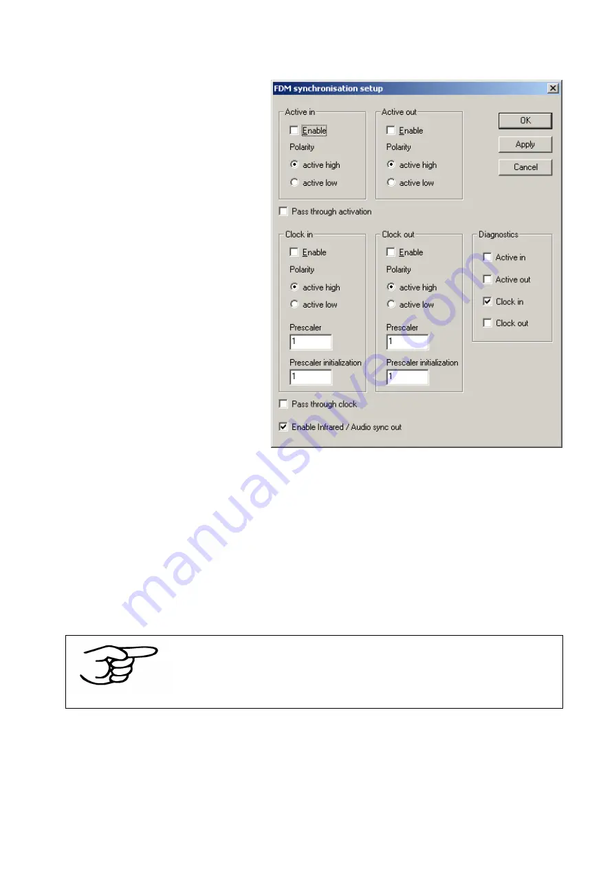
Configuration window of the FDM synchronization
OK
stores the settings in the
device configuration and closes the
dialog.
Apply
sets the configuration shown
in the dialog to the attached device
– without storing it to the device
configuration!
Cancel
closes the dialog without
storing anything.
Each signal (
Active in/out, Clock
in/out
) can be enabled, and the
polarity can be inverted.
By
Pass through activation
each
Signal can be forwarded from the
input to the output. If a signal is
passed through, the corresponding
output configuration has no effect;
the output level will be always the
same as the input level.
If the input signal polarity is set to
“
Active Low
”, the output will be the
inverted input signal.
Forwarding is done by hardware and thus works without any significant latency.
Clock in/out
can be also divided by a
Prescaler
. If the prescaler is set to 1, then the
system will start a measurement on each synchronization impulse. Higher prescaler values
work as divider. In case the prescaler is set to 2 then a measurement will be started on
every second impulse only. Set the
Prescaler initialization
value to the count of clock
events you want to be “ignored” before the first clock event passes the prescaler.
By
Enable Infrared / Audio sync
infrared- and video synchronization can be
enabled/disabled simultaneously. It is not possible to access them individually.
NOTE
Active in/out, Clock in/out
are active during recording only, in
preview mode of the data acquisition application they are disabled
automatically, even if you enable them in setup.
The
Diagnostics
box allows testing of the
Active in/out, Clock in/out
signals. The
“Active in” and “Clock in” checkboxes show the corresponding input levels; By checking or
unchecking the active out and clock out checkboxes you can set the level of the
corresponding output pins at the SYNC-IN and SYNC-OUT sockets. Note that the polarity
of the diagnostic checkboxes is affected by the corresponding “
Polarity
” radio buttons
(
active high/low
) of each signal.


