background image

32

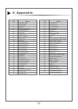
5. Appendix

1

2

4

5

6

8

9

1 0

1 1

1 2

13

14

15

16

17

18

19

2 0

2 1

2 2

23

24

25

30

31

32

33

34

35

36

37

38

3 9

40

41

42

4 3

4 4

4 5

46

4 7

48

4 9

50

51

52

5 3

SN

Name

Connection bar

Air outlet grill

Air deflector sponge 

Decorative panel

Insulation

Air deflector 4

Valve controller

Water valve

Insulation

Left-inner plate

Auxilary drain pan

Bearing fixture1

Bearing fixture2

Left-outer plate

Left support plate 1

Front panel

Air filter 1

Air inlet grill

Left support plate 2

Air inlet grill fixture

Coil fixture-left

Air filter 2

Fan blade

Air deflector supporter

Right-support plate 2

Motor fixture 1

Motor fixture 2

DC fan motor

Electric box cover

Insulation

Operation panel supporter

Rubber elbow

Right-outer plate

Magnetic

Magnetic fixture

Decorative panel

Coi l tem per at ur e se ns or

Air inlet/outlet sensor

3

7

SN

Name

Coil fixture-right

Rubber plug

Drain pan

Right-inner plate

Insulation

Coil

26

27

28

2 9

Air deflector 3

Air deflector 5

Air deflector 1

Air deflector 2

Right-support plate 1

ABS plate

Air guide plate 4 support plate

Electrical Installation plate

Circuit board

Содержание SLIM-C Series

Страница 1: ...R SLIM FAN COIL UNIT INSTRUCTION MANUAL INSTALLATION USER AND MAINTENANCE Thank you for purchasing our product Read this manual carefully before installing or operating your newequipment Make sure to...

Страница 2: ......

Страница 3: ...only 2 8 5 Water pipe connection 2 8 6 Filter 2 8 7 Insulation 2 9 Test run 2 9 1 Air purging 2 9 2 Pre Start up 2 9 3 Unit Start up 2 8 8 Setting up the condensate drainage system 3 Operation Instruc...

Страница 4: ...The precautions listed here are divided into following 3 types They all cover very important topics so be sure to follow them carefully Warning Caution Prohibition Children should be supervised to ens...

Страница 5: ...e damaged Do not insert any foreign objects into the air outlet grill when the fan motor is running Otherwise injury of person or unit damage might happen Do not clog air inlet or outlet by paper or a...

Страница 6: ...en supervision or instruction concerning use of the appliance by a person responsible for their safety 3 4 The appliance shall be installed in accordance with national wiring regulations 5 The type an...

Страница 7: ...ransfer area of this unit DC super low Casing in pre painted galvanized metal sheet complete with insulation grilles in high quality aluminium alloy Condensation collection tray with natural drainage...

Страница 8: ...ck that all accessories are packed inside the unit 2 2 Handling instructions Movement of the unit should be performed with care in order to avoid damage to the external structure and to the internal m...

Страница 9: ...nstallation 2 3 Dimensions T ithout motorized water valve he fan coil unit w 1094 1294 894 694 A m m Model no G1 2 16 22 28 32 G1 2 G1 2 G1 2 Connector size Net weight Kg SLIM C20 SLIM C30 SLIM C50 SL...

Страница 10: ...94 894 694 A m m Model no G1 2 16 22 28 32 G1 2 G1 2 G1 2 Connector size Net weight Kg 07 G1 2 A OUT IN G1 2 118 238 479 38 80 134 153 A 60 102 588 174 74 The fan coil with two way valve SLIM C20 SLIM...

Страница 11: ...08 Net weight K g 2 Installation Model Connector A mm 1094 1294 894 694 G1 2 16 22 28 32 SLIM C20 SLIM C35 SLIM C50 SLIM C60 G1 2 G1 2 G1 2 The fan coil with three way valve...

Страница 12: ...5 Unit Installation For floor installation the minimum clearance is 80mm between the floor and the bottom of the unit 20mm from unit side to the wall for easy removal of side panels and 140mm around...

Страница 13: ...s Power supply to the unit must be off before installation or maintenance work starts Measuring reel Accessory box Take out the accessory box as shown in below pictures Accessory box Quantity Name Rem...

Страница 14: ...w Gasket Sensor fixture 1 2 4 2 1 1 Drain pipe Plastic hose clamp Sealing gasket Spring washer Screws 1 1 2 2 4 Before op erati ng this uni t plea se read thi s manual an d keep it wel l for futu re r...

Страница 15: ...cessory Please put the positioning board up against the wall 1294 1094 794 594 964 764 564 364 Model A B SLIM C60 SLIM C50 SLIM C35 SLIM C20 4 5 6 2 8 2 Take off the air outlet grill 1 2 Take out the...

Страница 16: ...by two expansion bolts in each side To fasten the unit to a wooden wall use suitable bolts 2 Mark on the wall where the mounting holes will be drilled Drill the wall with a power drill Put the 8 expa...

Страница 17: ...close to base board Installation of baffle plate for feet 2 8 4 Installation of feet for the models with feet included only Fix the feet onto the unit by fastening the screws on two sides of feet Aft...

Страница 18: ...eyond the range of side panel otherwise the side panel can t be installed back water outlet water inlet water inlet water outlet Water pipes passing through the ground Water pipes passing through the...

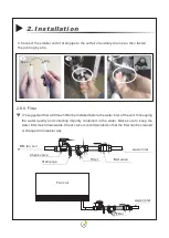
Страница 19: ...y turning round 4 5 6 1 2 3 1 Take off the sealing cover of water inlet otulet pipe Installation steps 2 inlet outlet water pipe Choose the water pipe in proper length to connect the unit to water sys...

Страница 20: ...amaged by turning round 3 4 5 1 2 1 Take off the sealing cover of water inlet otulet pipe Installation steps 2 inlet outlet water pipe Choose the water pipe in proper length to connect the unit to wat...

Страница 21: ...sure to keep the water Check valve is recommended so that the filter can be cleaned or changed in an easier way be filter mesh downwards BM fan coil water inlet Ball valve Filter Check valve drain pi...

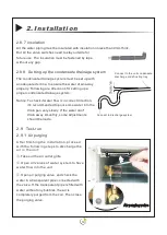
Страница 22: ...e unit Open air purging valve and check the water in a transparent pipe connected with the valve If the transparent pipe is filled with water without any bubbles the air is completely purged from the...

Страница 23: ...lation requirement Check voltage of the unit power supply and make certain voltage is within authorized limitations Make sure the unit is properly grounded Check the presence of protective and breakin...

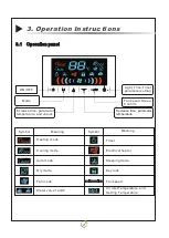
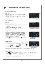
Страница 24: ...speed Sleep Confirm increase time parameter temperature and unlock Mode ON OFF Decrease time parameter temperature Symbol Meaning Heating mode Cooling mode Auto mode Dry mode Fan mode Water valve1 an...

Страница 25: ...the unit does not work when standby but only shows the room temperature The unit will recover its latest working settings automatically after power failure 2 Standby 1 Power on but not press to turn o...

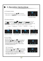
Страница 26: ...unit is standby press for 3 seconds and set the timer by and The system will automatically save the settings after 3 seconds with lighting up Temperature Setting Super low Fan speed Low Fan speed Med...

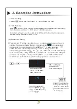
Страница 27: ...re is no instruction in 10 seconds In order to save and back press after setting a parameter or serial number Pressing button and set the timer to zero to cancel the timer and Parameter 1 press or to...

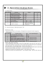
Страница 28: ...Super low fan speed of heating Valve functions 485 communication Ps Actual fan speed Setting fan speed 100 12 Failure code Failure code will flash on the display Multiple failure code will come in se...

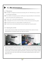
Страница 29: ...ely The maintenance work must be performed by qualified Failure code in this manual is helpful to find out and fix the failure of the unit personnel not run for a lont time 4 Maintenance To ensure the...

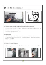
Страница 30: ...m occasionally to ensure the performance of the unit Please do air purging work as per 2 9 1 Please drain out the water in the system if the unit for a long tine Occassionally check whether there is a...

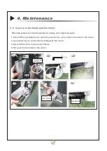
Страница 31: ...ox pull out the connector of the motor 2 Use a Allen key to unlock the fan blade with fan motor 3 Take off the screw for fan motor fixture 4 Take out the fan blade or fan motor When fan system is not...

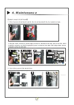
Страница 32: ...box 4 5 6 Motor connector three wayvalveconnector Null wire of power supply connector powersuppl yconnector Firewireofelectrical Wired controller connector with WIFI function Airinlettemperature sens...

Страница 33: ...e connector wired controller connector air inlet temperature sensor connector and water inlet temperature sensor connector on the circuit board Plastic screws Motor connector three wayvalveconnector N...

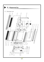
Страница 34: ...31 5 Appendix 5 1 Exploded view...

Страница 35: ...grill Left support plate 2 Air inlet grill fixture Coil fixture left Air filter 2 Fan blade Air deflector supporter Right support plate 2 Motor fixture 1 Motor fixture 2 DC fan motor Electric box cov...

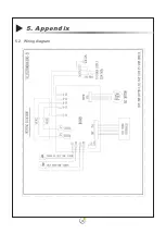
Страница 36: ...33 5 2 Wiring diagram 5 Appendix...

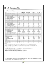
Страница 37: ...m temperature 20 c Heating Water inlet 70 outlet60 Room temperature 20 d Air flow measured with clean filter e Noise tested as per ISO23741 2 and ISO 7779 2001 The specification are subject to change...

Страница 38: ...NOTES...

Страница 39: ......

Страница 40: ...www ZAN TIA com...

Отзывы: