


H. ZANDER GmbH & Co. KG • Am Gut Wolf 15 • 52070 Aachen • Germany • Tel +49 241 9105010
Fax +49 241 91050138 • [email protected] • www.zander-aachen.de
26
Operating manual ZX09/20/21-Series
5.5.4 Connection of the analog inputs
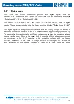
Fig. 16 shows an example of how to connect the analog input to a ZX09A controller for
a voltage measurement. The signal generated by the sensor is connected to terminals
A+ and 0V via a shielded cable. The supply line of the analog input must be made with
a shielded cable. Connect the cable screen on one side as close as possible to the
terminals of the control system with low impedance to a screen rail which is at PE
potential (see fig.16). The cables must be laid as far away as possible from cables
subject to interference. The connection of the analog inputs on the device variants
ZX09B, ZX09C, ZX09D and ZX09E is carried out according to these instructions. The
terminals A1+ to A4+ are fixed inputs (ZX09B/D: voltage inputs; ZX09C/E: current
inputs) and the terminals A5+ and A6+ are adjustable inputs between current and
voltage input.
Fig. 16: Connection of a analog input (ZX09A)
Analog Input
20mA
10V A
1
+ 0 V
Shield rail
(PE)
0V
0 - 10V
Switch
Sensor


