background image

33

ZABER TECHNOLOGIES INC.

11. Troubleshooting X-Series Motion Devices

The following sections contain tips for troubleshooting common problems.  If the device is unable
to communicate, and it is operating erratically, a manual factory reset can be performed through
the following steps.  Note that this will reset most settings.

1. Power Off the device

2. Push and hold the knob for the first Axis (if applicable)

3. Power On the device

4. Continue to hold the knob in until the blue LED is lit (~5 seconds), then release.

The device has been returned to its factory defaults and can be configured as per the steps in
Initial Setup.

Содержание X-MCB1 Series

Страница 1: ...Simplifying Motion Control Fri Nov 03 2017 ZABER TECHNOLOGIES INC X MCB1 Series User s Manual Single axis stepper motor controllers chopper drive with I O ...

Страница 2: ... 1 1 Power 5 1 2 RS 232 Communications 5 1 3 USB Communications 5 1 4 Motor Interface 5 1 5 Inputs Outputs 5 2 Indicators 5 3 Communications 6 Installation 6 1 Daisy Chaining Devices 6 2 Physical Installation 7 Manual Control 7 1 Velocity Mode 7 2 Displacement Mode 7 3 Summary of knob functionality 8 Trajectory Control and Behaviour 8 1 Software Position Limits 8 2 Movement Speed 9 Quick Command R...

Страница 3: ...rors 11 5 Slipping and Stalling 12 Warranty and Repair 12 1 Standard products 12 2 Custom products 12 3 How to return products 13 Email Updates 14 Contact Information 15 Appendix A Available Communications Ports 15 1 Finding Installed Serial Ports 15 1 1 Windows 15 1 2 Linux 15 1 3 OSX 16 Appendix B USB Driver Installation 16 1 Compatible Devices 16 2 Windows 16 2 1 Download 16 2 2 Windows Vista 7...

Страница 4: ...III ZABER TECHNOLOGIES INC 17 Product Drawing 18 Specifications 55 56 ...

Страница 5: ...an occur to stepper motor products when operated with significantly higher than rated current The X MCB1 controller can provide up to 2A of current to a peripheral BEFORE CONNECTING A NEW DEVICE to the X MCB1 controller it is important to set the correct motor parameters in the controller Please check the rated current for any peripheral device before changing the current settings on the X MCB1 fr...

Страница 6: ...od to check that they are correct especially if you receive multiple peripherals of different models 1 Power up all integrated devices and controllers and daisy chain them together using the RS 232 Prev and Next connectors see Daisy Chaining Devices for more details Many products share power through the daisy chain cables The power indicator on each should light up 2 Download and install Zaber Con...

Страница 7: ... This is achieved by sending the home T 1 command to the individual unit or all units Until this is done most devices will only allow motion in one direction towards the sensor If it is not possible in your application to home the device after every power up see the tools parking T 65 command Parking allows the device to be turned off and then used at a later time without first having to home the ...

Страница 8: ...ce for all Commands and Settings that the device has To access the help send 1 help for help with Device 1 The device number must be specified in the help command This feature is only available in the ASCII protocol The device will respond with a detailed description on how to access specific information about commands and replies as shown below 01 0 OK IDLE WR 0 01 0 COMMAND USAGE 01 0 stop stop ...

Страница 9: ...evice 5 1 1 Power Pin Description 1 24 48V 2 GND Note Zaber s power supplies ground this pin to AC Earth Note To prevent damage to the device due to static buildup the device should be properly grounded The power supplies Zaber provides for X Series devices are non isolated and thus ground the device chassis to Earth via the negative terminal of the power supply If for any reason you are using an ...

Страница 10: ...round 3 Receive Transmit 4 Transmit Receive Default Settings Baud Rate 115200 Protocol Zaber ASCII Specifications Supported Protocols Zaber ASCII Zaber Binary Supported Baudrates 9600 19200 38400 57600 115200 Bits 8 Parity None Stop Bits 1 Flow Control None 5 1 3 USB Communications Specifications ...

Страница 11: ...V 2 D Limit Sensor or Encoder Error 3 C Limit Sensor 4 Away Limit Sensor 5 Home Limit Sensor 6 Ground 7 Motor B1 8 Motor A1 9 Encoder 5V 10 Encoder A 11 Encoder B 12 Encoder Index 13 Encoder Ground 14 Motor B2 15 Motor A2 NOTE The limit sensor inputs are pulled up to the internal supply rail and are designed to be pulled low by an open collector NOTE All sensor and encoder inputs are non isolated ...

Страница 12: ... ZABER TECHNOLOGIES INC 5 1 5 Inputs Outputs Pin Description 1 Digital In 1 2 Digital In 2 3 Digital In Common 4 Digital Out 1 5 Digital Out 2 6 Digital Out Common 7 Analog In 1 8 Analog In 2 9 5V 10 GND ...

Страница 13: ... power for low current I O applications The pins can source up to 200 mA of current If additional current is needed an external power supply is required Note that this output is not isolated Mating Products TE Connectivity 1 1986692 0 or 1 284506 0 5 2 Indicators Green Power PWR On Controller is operational Blinking at 2Hz The power supply voltage or device temperature is out of range Fading in an...

Страница 14: ...very 1 sec or the encoder has encountered a read error and raised the FQ warning flag 5 short flashes every 2 sec 5 3 Communications The X MCB1 supports multiple communications interfaces and processes commands through the currently active interface which is determined by the interface priorities Enabling or connecting a higher priority interface will cause any commands received over the lower pri...

Страница 15: ...nstall the necessary drivers automatically when the cable is plugged in for the first time If the computer reports that the driver installation was unsuccessful you can download the drivers for Windows Mac or Linux here Installation instructions and troubleshooting information are available for each operating system here You may need to use a cable extension to reach your computer There is no need...

Страница 16: ...ply only needs to be connected to one device in the chain Whenever a device is added or removed from a chain a renumber T 2 command should be sent to prevent device address conflicts To daisy chain X Series devices with T Series and A Series devices Ensure all devices are set to the same communication protocol and baud rate before connecting them If any T Series devices will be in the chain then t...

Страница 17: ... or 2 pitch optical breadboards using M6 or 1 4 screws respectively or for use on a desk or table It can be mounted to a breadboard in two configurations TIP When mounting on edge it is easier to connect the cables nearest to the adapter plate after mounting the unit to the optical breadboard ...

Страница 18: ... TECHNOLOGIES INC In situations where mounting is not necessary 4 adhesive rubber feet are provided which can be applied to the underside of the unit to prevent it from sliding on the surface of a desk or table ...

Страница 19: ...ents per revolution allowing devices to be controlled without the use of a computer There are two manual movement modes available Velocity and Displacement Switch between these modes by holding down the knob for 1 second or by configuring the knob mode T 109 setting On power up the device will only travel towards the motor from its start up position until the home position is reached Once the devi...

Страница 20: ...f knob distance T 110 is set to 0 each detent of the knob will move to the next index position similar to move index T 78 movements The device moves at the speed specified by the maxspeed T 42 setting or the slower of maxspeed T 42 and limit approach maxspeed T 41 if the device has not been homed If there are fewer than knob distance T 110 microsteps to the end of travel and another move is reques...

Страница 21: ...tus and various speed settings If the device has not been initialized by the home T 1 command or by moving towards the home end of the device movement speed will be constrained to fail safe values The home status of the device can be determined by reading the limit sensor triggered T 53 setting the binary command additionally requires a value of 103 Movement speed of the device is specified below ...

Страница 22: ... the parameters in the set need to be provided Command Scope Parameter s Returns Firmware Versions Description calibration Device Refer to the documentation 0 6 24 Configure linear encoder calibration estop Axis 0 6 06 Instantly stops motorized movement get Device and Axis setting value 6 06 Retrieves the current value of the device or axis setting help Device commands reply warnflags enums comman...

Страница 23: ...0 6 06 Restores common device settings to their default values tools echo Device message 0 6 06 Echoes the provided message if any back to the user tools findrange Axis 0 6 10 Uses the home and away sensors to set the valid range of the axis tools gotolimit Axis limit dir action update 0 6 06 Moves the axis to a limit sensor and performs the provided actions tools parking Device state park unpark ...

Страница 24: ... the axis cloop counts Axis Yes 6 06 The number of counts generated by the encoder for one full revolution cloop displace tolerance Axis Yes 6 19 The minimum deviation in the position of a stationary axis that will register as a displacement cloop duration max Axis Yes 6 17 The duration for attempting fine position correction cloop mode Axis Yes 6 06 The closed loop slip stall and displacement det...

Страница 25: ...24 The calibrated counts of the axis encoder encoder dir Axis Yes 6 06 Inverts the counting direction for the axis encoder encoder error Axis No 6 17 Position error measured by encoder encoder fault type Axis Yes 6 24 The type of fault signal provided by the encoder encoder filter Axis Yes 6 06 Enable and set up digital filtering of the encoder inputs encoder index count Axis Yes 6 06 The recorded...

Страница 26: ...preset Axis Yes 6 06 The default position of the home sensor limit home state Axis No 6 06 The state of the home sensor limit home triggered Axis No 6 06 Whether the home sensor has been triggered previously limit home type Axis Yes 6 06 The type of home sensor connected limit away action Axis Yes 6 06 Automatic limit switch action limit away edge Axis Yes 6 06 Sensor edge to align action to limit...

Страница 27: ... sensor has been triggered previously limit d type Axis Yes 6 06 The type of d limit sensor connected limit max Axis Yes 6 06 The maximum position the device can move to measured in microsteps limit min Axis Yes 6 06 The minimum position the device can move to measured in microsteps limit start pos Axis Yes 6 19 Start up position of the axis limit swapinputs Axis Yes 6 06 Reverses the limit positi...

Страница 28: ...the device s firmware 9 2 Binary Protocol The following table offers a quick command reference for the X MCB1 For convenience you may sort the table below by instruction name command number or reply number Follow the links to view a detailed description of each instruction or refer to the Binary Protocol Manual Instruction Name Command Command Data Command Type Reply Data Reset 0 Ignored Command N...

Страница 29: ...e Mode 40 Mode Setting Mode Set Home Speed 41 Speed Setting Speed Set Target Speed 42 Speed Setting Speed Set Acceleration 43 Acceleration Setting Acceleration Set Maximum Position 44 Range Setting Range Set Current Position 45 New Position Setting New Position Set Home Offset 47 Offset Setting Offset Set Alias Number 48 Alias Number Setting Alias Number Return Device ID 50 Ignored Read Only Setti...

Страница 30: ... Pin States Return Analog Input Count 75 Ignored Read Only Setting Pin Count Read Analog Input 76 Pin Number Command Voltage Return Analog Output Count 77 Ignored Read Only Setting Pin Count Move Index 78 Index Number Command Final Position Set Index Distance 79 Distance Setting Distance Set Cycle Distance 80 Distance Setting Distance Return Encoder Count 82 Ignored Read Only Setting Encoder Count...

Страница 31: ... 113 Acceleration Setting Acceleration Set Deceleration Only 114 Deceleration Setting Deceleration Set Move Tracking Mode 115 Tracking Mode Setting Tracking Mode Set Manual Move Tracking Disabled Mode 116 Tracking Mode Setting Tracking Mode Set Move Tracking Period 117 Tracking Period Setting Tracking Period Set Closed Loop Mode 118 Closed Loop Mode Setting Closed Loop Mode Set Slip Tracking Perio...

Страница 32: ...itry as long as the current draw remains below 200 mA 10 1 Digital Inputs The digital inputs on the X MCB1 are fully opto isolated and bi directional giving added flexibility when interfacing to external equipment The two examples below demonstrate how the common line can be connected to a power rail or to ground depending on the application Each digital input contains an internal current limiting...

Страница 33: ...tput from another device Reading the inputs is accomplished by sending the unit an io get command as shown below 1 io get di 01 0 OK IDLE 0 0 1 0 1 io get di 1 01 0 OK IDLE 0 The first command queries all inputs on the device and shows that input 3 is high and all others are low The second command queries a specific input on the device in this case input 1 which is low ...

Страница 34: ...nt draw for example a relay an external switching transistor is required as shown in example 2 The digital outputs are set through the io set command as shown below 1 io set do 1 1 01 0 OK IDLE 0 1 io set do 1 0 01 0 OK IDLE 0 The first command sets the first digital output which would cause the LED in example 1 above to glow The second command clears the output turning off the LED TTL Outputs Add...

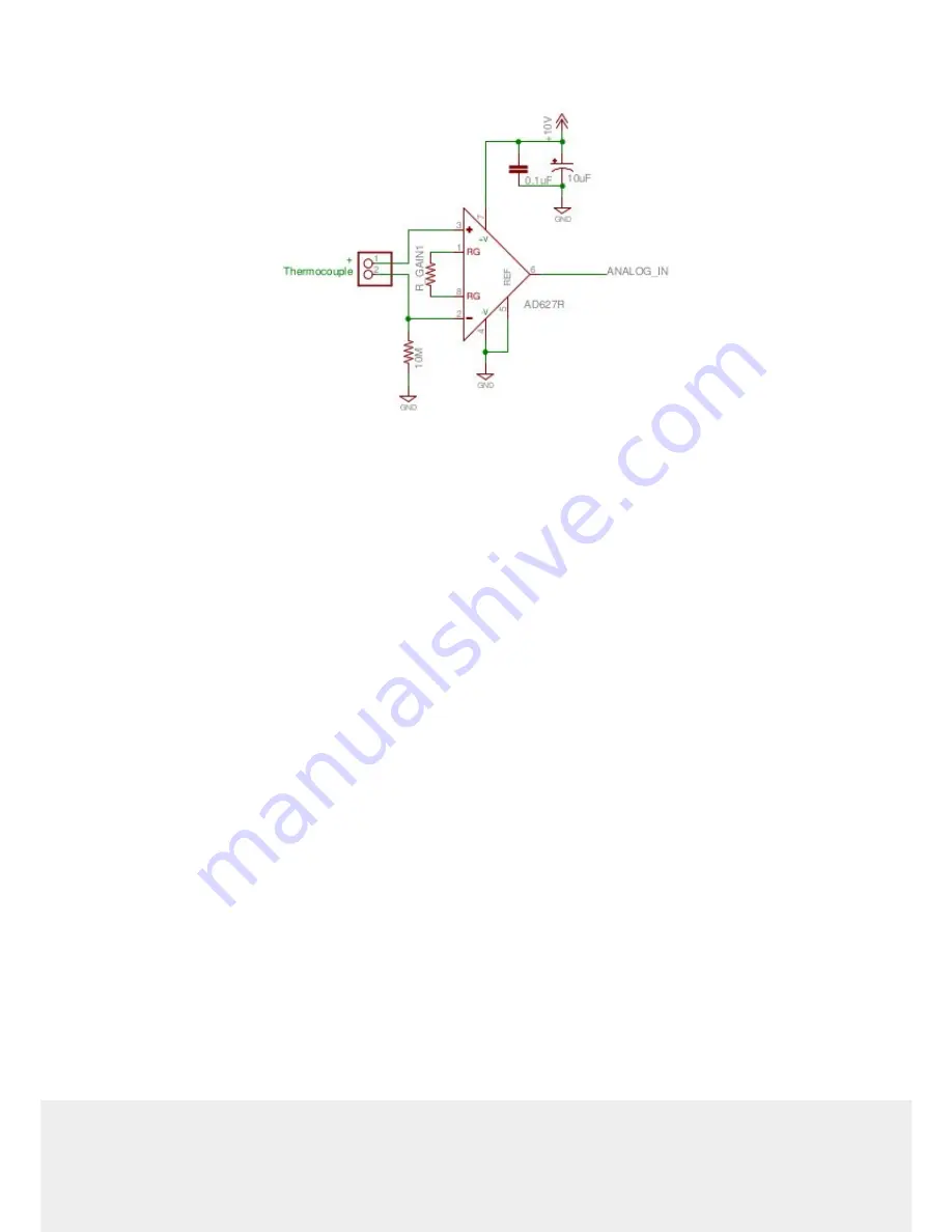
Страница 35: ...current limits are adhered to 10 3 Analog Inputs The analog inputs on the X MCB1 accept and display voltages in the range of 0 10V In order to measure other analog variables a transducer or sensor is required that outputs an appropriate voltage range As transducers typically provide low voltage signals an amplifier and buffer circuit is required to interface a transducer to the X MCB1 The referenc...

Страница 36: ... input of the X MCB1 and a negative full scale produces 0V The OP97 op amp provides an offset of 5V to the amplified value so that no load on the instrument produces an output of 5V The reference circuit below demonstrates interfacing a thermocouple to the X MCB1 Depending on the application an offset voltage may need to be provided ...

Страница 37: ...ically a manual factory reset can be performed through the following steps Note that this will reset most settings 1 Power Off the device 2 Push and hold the knob for the first Axis if applicable 3 Power On the device 4 Continue to hold the knob in until the blue LED is lit 5 seconds then release The device has been returned to its factory defaults and can be configured as per the steps in Initial...

Страница 38: ...rational range of the device This can be read from the device with the get system voltage command The device temperature is within range This can be read from the device with the get system temperature command The driver is not disabled If the driver is disabled the result of the warnings command will contain the FD flag Green LED Off The device is not powered Check the supply connections and powe...

Страница 39: ...nst the ends of travel The position encoder has de synchronized Reset the device by power cycling it or sending the system reset T 0 command then re initialize it with the home T 1 command The device is moving very slowly It used to move faster The speed settings may have been changed inadvertently Send a system restore T 36 command The device makes louder than normal noise during travel and is fr...

Страница 40: ...the Yellow LED does not come on or flash There are several things that should be checked Make sure the correct serial port is selected Try selecting other serial ports in the software Check the baud rate hand shaking parity stop bit etc when configuring the serial communications software The required settings are listed in the RS 232 Communications section above Make sure there are no bent pins in...

Страница 41: ... port is not configured with a termination character it often defaults to linefeed If problems are encountered when using custom software try using one of the demo programs from the Zaber website to verify that the hardware works The device does not behave as expected when software sends it a series of commands The computer might be set to Unicode This is common for languages that use non Latin ba...

Страница 42: ...stalling Try removing all external loads If the device now extends and retracts normally the problem is excessive load Try to reduce the load and ensure the load is less than the maximum thrust A higher thrust or torque can be achieved by lowering the speed of the device using the maxspeed T 42 setting If a device is stalling with no external load at default speed and acceleration settings then it...

Страница 43: ...us to receive an RMA number The RMA form contains instructions for packing and returning the device The specified RMA number must be included on the shipment to ensure timely processing 13 Email Updates If you would like to receive our periodic email newsletter including product updates and promotions please sign up online at www zaber com news section Newsletters typically include a promotional o...

Страница 44: ...INC 15 Appendix A Available Communications Ports 15 1 Finding Installed Serial Ports 15 1 1 Windows 1 Open Search or Run from the Start Menu or Taskbar type Device Manager and press enter 2 Expand the Ports COM LPT category ...

Страница 45: ... command dmesg grep E ttyU S The response will be similar to the following 2 029214 serial8250 ttyS0 at I O 0x3f8 irq 4 is a 16550A 2 432572 00 07 ttyS0 at I O 0x3f8 irq 4 is a 16550A 2 468149 0000 00 03 3 ttyS4 at I O 0xec98 irq 17 is a 16550A 13 514432 usb 7 2 FTDI USB Serial Device converter now attached to ttyUSB0 This shows that there are 3 serial ports available ttyS0 ttyS4 and ttyUSB0 a ...

Страница 46: ...mbashare Notice that dialout is not in the list A user can be added to the dialout group with the following command sudo adduser USER dialout Group membership will not take effect until the next logon 15 1 3 OSX 1 Finding devices Open a terminal and execute the following command ls dev cu serial The response will be similar to the following dev cu usbserial FTB3QAET dev cu usbserial FTEJJ1YW This ...

Страница 47: ...nected and configured following the instructions on this page they will create a virtual serial COM port on your computer for communication If you are trying to connect one of Zaber s X USBDC T USBDC or T USB serial to USB adaptors go to the Software page for instructions 16 2 Windows Microsoft Windows requires a driver to be installed for the USB connection to operate correctly ...

Страница 48: ... your version of Windows 16 2 2 Windows Vista 7 8 1 Windows will detect the device connection and attempt to automatically install drivers After a minute or so this will fail with a message that the device is not working correctly Continue on with the steps below 2 Right click on My Computer and select Manage 3 Select Device Manager from the list on the left Under Other devices you should see an e...

Страница 49: ...45 ZABER TECHNOLOGIES INC 5 Choose Browse my computer for driver software ...

Страница 50: ...46 ZABER TECHNOLOGIES INC 6 Click the Browse button and select the location where you extracted the driver to ...

Страница 51: ...47 ZABER TECHNOLOGIES INC 7 Click Next ...

Страница 52: ...48 ZABER TECHNOLOGIES INC 8 Click Install 9 Click Close Your controller is now available and should appear in the Ports COM LPT section of the Device Manager ...

Страница 53: ...49 ZABER TECHNOLOGIES INC 16 2 3 Windows XP 1 Windows will automatically detect the connection of the controller 2 Once the New Hardware Found wizard starts select No not this time and click next ...

Страница 54: ...r and select Manage 2 Select Device Manager from the list on the left 3 Under Unknown Devices you should see an entry with the name of the Zaber controller that is connected 4 Right click on this entry and select Update Driver 3 Select Install from a specific location and click Next ...

Страница 55: ...51 ZABER TECHNOLOGIES INC 4 Click the Browse button and select the location where you extracted the driver to 5 Click Next ...

Страница 56: ...52 ZABER TECHNOLOGIES INC 6 Select Continue Anyway 7 Click Finish Your controller is now available and should appear in the Ports COM LPT section of the Device Manager ...

Страница 57: ...his case dev ttyACM0 94929 668171 usb 3 4 1 3 new full speed USB device number 92 using xhci_hcd 94929 686563 usb 3 4 1 3 New USB device found idVendor 2939 idProduct cafe 94929 686572 usb 3 4 1 3 New USB device strings Mfr 1 Product 2 SerialNumber 3 94929 686577 usb 3 4 1 3 Product X MCB2 94929 686581 usb 3 4 1 3 Manufacturer Zaber Technologies Inc 94929 686585 usb 3 4 1 3 SerialNumber 1 94929 68...

Страница 58: ... modem manager will try to query the device when it is connected This won t affect device operation but can cause the port to be unavailable for several seconds 16 4 OS X USB Communications Device Class CDC devices are supported in 10 5 and above No special configuration or drivers are needed The controller will appear as a tty usbmodem device The kernel log available through dmesg details the dev...

Страница 59: ...55 ZABER TECHNOLOGIES INC 17 Product Drawing ...

Страница 60: ...410 mA 2 000 mA peak Motor Connection D Sub 15 female Default Resolution 1 64 of a step Data Cable Connection Locking 4 pin M8 USB B Manual Control Indexed knob with push switch Axes of Motion 1 LED Indicators Power Error Motor Encoder Operating Temperature Range 0 to 50 C RoHS Compliant Yes CE Compliant Yes Limit Sensors per Axis 4 Isolated Digital Input 2 Isolated Digital Output 2 Analog Input 2...

Отзывы: