rdq-6 instruction manual
z-systems audio laboratories
16
slope of 1 giving the widest bandwidth, and a value of 12 giving the narrowest bandwidth.
Figure 15 illustrates this relationship clearly -- as we increase the slope parameter, the 3-dB
points will gradually move toward 1000 Hz from the left and from the right and the filter gets
narrower and narrower.
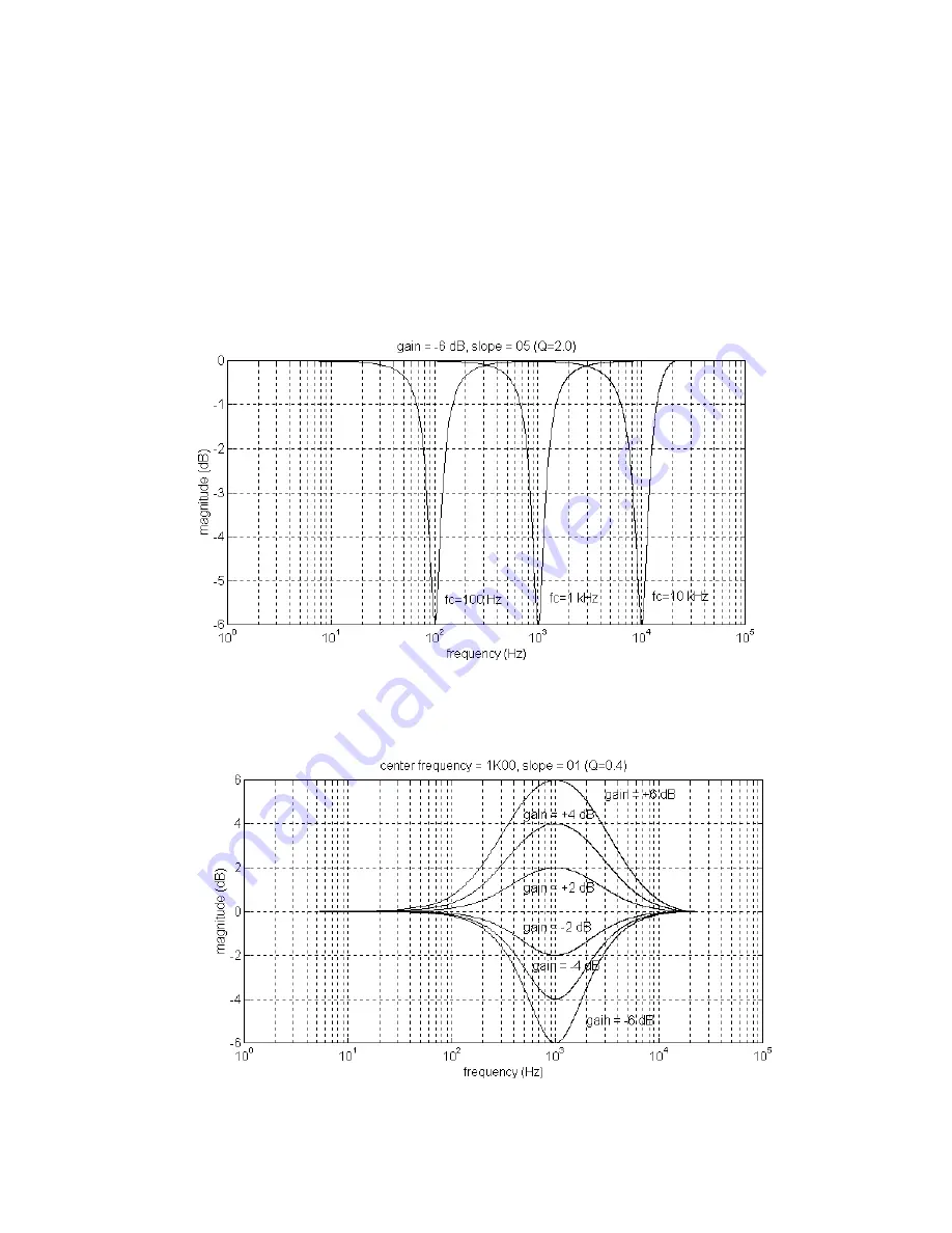
Whereas Figure 15 showed the effect of changing the slope while holding the center
frequency and gain constant, Figure 16 shows the effect of holding the slope and gain
constant while moving the center frequency. Figure 16 shows a family of frequency response
curves for a slope equal to 05, a gain of –6 dB and center frequencies of 100 Hz, 1 kHz, and 10
kHz, respectively. Notice that the filters have identical shapes when viewed on a logarithmic
frequency axis.
F
IGURE
16
Finally, Figure 17 shows the effect of holding the slope and the center frequency constant
while varying the gain. In particular, the center frequency is 1000 Hz, the slope is the
minimum allowed, 01, and the gain is varied between –6 dB and +6 dB.
F
IGURE
17


