FORM 160.55-O1 (920)
125
YORK INTERNATIONAL
4
Any malfunctions which occur during
“STOP/ RESET” are also displayed.
When the chiller is shut down, the prerotation vanes
will close automatically to prevent loading the com-
pressor on start-up. When the chiller starts to operate,
the following automatic sequences are initiated: (Re-
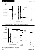
fer to Fig. 54 & 55, “Operation Sequence Timing
Diagram”.)
1. The OptiView Control Center display message
will read
“SYSTEM PRELUBE”
for the first
30 seconds of the starting sequence. (3 min. if
Microboard Program Switch SW1-3 is “ON”;
“OFF” = 30 seconds.)
2. The compressor vent line solenoid valve will open
after the first 5 minutes of unit operation. The so
-
lenoid will close automatically after the compressor
shuts down.
3. The 1R-1 contacts of the 1R start relay will remain
open for the first 30 seconds of oil pump operation.
These contacts will close, starting the compressor
motor and the condenser water pump at the end of
the 30 second period.
4. The chilled liquid pump contacts will close, starting
the chilled liquid pump to allow liquid flow through
the cooler when the “
COMPRESSOR
” start switch
is energized.
5. After the first 30 seconds of operation, the com
-
pressor will start and the Graphic Control Center
display message will read
“SYSTEM RUN”.
Chiller Operation
After the compressor reaches its operating speed the
prerotation vanes will begin to open under the control
of the micro processor board or the logic section of the
Variable Speed Drive which senses the leaving chilled
liquid temperature. The unit capacity will vary to main-
tain the leaving chilled liquid temperature setpoint. The
prerotation vanes are modulated by an actuator under
the control of the microprocessor board or logic section
of the Variable Speed Drive. The vane control routine
employs proportional plus derivative (rate) control ac-
tion. A drop in chilled liquid temperature will cause
the actuator to close the prerotation vanes (and also
decreases the speed of the motor if equipped with a
Variable Speed Drive) to decrease chiller capacity. When
the chilled liquid temperature rises, the actuator will open
the prerotation vanes and increase the compressor motor
speed of the chiller (if controlled by the Variable Speed
Drive), to increase the capacity of the unit.
However, the current draw (amperes) by the compressor
motor cannot exceed the setting of the “
% CURRENT
LIMIT
” at any time during the unit operation, since the
Graphic Control Center 30 to 100% three phase peak
current limit software function, plus the 3 phase 100%
solid state overload current limiter (CM-2) on Electro-
Mechanical Starter applications or the solid state starter
current limit function will override the temperature con-
trol function (or the logic section of the Variable Speed
Drive) and prevent the prerotation vanes from opening
beyond the “
% CURRENT LIMIT
” setting.
If the load continues to decrease, after the prerotation
vanes are entirely closed, the chiller will be shut down
by the Low Water Temperature control (LWT) function
which is displayed on the Control Center as:
“LEAVING
CHILLED LIQUID – LOW TEMPERATURE”.
This occurs when the leaving water temperature falls
to programmed shutdown setpoint or 36°F, whichever
is higher.
If the temperature setpoint has been
reprogrammed within the last 10 min-
utes, the LWT cutout is 36°F for 10
minutes.
Condenser Water Temperature Control
The YORK Millennium chiller is designed to use
less power by taking advantage of lower than design
temperatures that are naturally produced by cooling
towers throughout the operating year. Exact control of
condenser water, such as a cooling tower bypass, is not
necessary for most installations. The chiller requires only
that the minimum condenser water temperature be no
lower than the value determined by referring to Fig. 56.
At start-up the entering condenser water temperature may
be as much as 25°F colder than the standby return chilled
water temperature. Cooling tower fan cycling will nor-
mally provide adequate control of the entering condenser
water temperature on most installations.
Содержание YT Millennium
Страница 11: ...FORM 160 55 O1 920 11 YORK INTERNATIONAL THIS PAGE INTENTIONALLY LEFT BLANK TO MAINTAIN FORMAT...
Страница 35: ...FORM 160 55 O1 920 35 YORK INTERNATIONAL THIS PAGE INTENTIONALLY LEFT BLANK TO MAINTAIN FORMAT 2...
Страница 37: ...FORM 160 55 O1 920 37 YORK INTERNATIONAL THIS PAGE INTENTIONALLY LEFT BLANK TO MAINTAIN FORMAT 2...
Страница 63: ...FORM 160 55 O1 920 63 YORK INTERNATIONAL THIS PAGE INTENTIONALLY LEFT BLANK TO MAINTAIN FORMAT 2...
Страница 67: ...FORM 160 55 O1 920 67 YORK INTERNATIONAL 2 THIS PAGE INTENTIONALLY LEFT BLANK TO MAINTAIN FORMAT...
Страница 73: ...FORM 160 55 O1 920 73 YORK INTERNATIONAL THIS PAGE INTENTIONALLY LEFT BLANK TO MAINTAIN FORMAT 2...
Страница 111: ...FORM 160 55 O1 920 111 YORK INTERNATIONAL THIS PAGE INTENTIONALLY LEFT BLANK TO MAINTAIN FORMAT 2...
Страница 136: ...YORK INTERNATIONAL 136 FORM 160 55 O1 920 Operational Maintenance LD00470 FIG 61 ASSEMBLY OF DEHYDRATOR...
Страница 155: ...FORM 160 55 O1 920 155 YORK INTERNATIONAL NOTES...

