YORK INTERNATIONAL
134
FORM 160.55-O1 (920)
System Components Description
Victaulic grooves are welded to the water boxes. These
nozzle connections are suitable for Victaulic couplings,
welding or flanges (300
PSI
has flanges). 1/2" coupling
and separable well are located in the entering and leaving
chilled liquid nozzles for temperature sensing elements.
Plugged 1/2" or 3/4" drain and vent connections are
provided in each water box.
COOLER
- The cooler is a horizontal, flooded, shell-
and-tube type, with a distribution system consisting
of a distributor trough to give uniform distribution
throughout the shell length and a perforated distributor
plate, located under the entire tube bundle, to equally
distribute refrigerant. Intermediate steel tube supports
are spaced at intervals of less than four feet. Highly ef-
ficient, aluminum mesh eliminators are located above
the tube bundle to prevent liquid refrigerant carryover
into the compressor.
A liquid level sight glass is conveniently located on the
side of the cooler to aid in determining proper refrig-
erant charge.
CONDENSER
- The condenser is a horizontal, shell-
and-tube type, with a discharge gas baffle to prevent di
-
rect high velocity impingement on the tubes. This baffle
is also used to distribute the refrigerant gas flow properly
for most efficient heat transfer. A purge connection is
located in the condenser for efficient elimination of
noncondensibles. Intermediate steel tube supports are
spaced at intervals of less than four feet.
REFRIGERANT FLOW CONTROL
- The flow con
-
trol chamber is welded to the bottom of the condenser to
allow complete drainage of liquid refrigerant from the
condenser. The chamber contains a single fixed-orifice
flow control with no moving parts.
BURSTING DISC
- A 2" or 3" frangible carbon burst-
ing disc relief device is located in the compressor suc-
tion line.
SOLID STATE STARTER (OPTIONAL)
The Solid State Starter is a reduced-voltage liquid cooled
starter that controls and maintains a constant current
flow to the motor during start-up. The starter is mounted
on the chiller. The power wiring from the starter to the
motor and from the starter control transformer to the
Control Center is factory wired and tested. Available
for 200-600V-3Ph-60/50 Hz power; 2 or 3 barrel lug
connections per phase are provided on the starter. The
starter enclosure is NEMA Type1 and is provided with
a hinged door with lock and key.
VARIABLE SPEED DRIVE (OPTIONAL)
A 460V-3ph-60/50 Hz Variable Speed Drive can be fac-
tory packaged with the chiller. It is designed to vary the
compressor motor speed and prerotation vane position
by controlling the frequency and voltage of the electrical
power to the motor. Operational information is contained
in Form 160.00-O1. The control logic automatically
adjusts motor speed and compressor prerotation vane
position for maximum part load efficiency by analyzing
information fed to it by sensors located throughout the
chiller.
Содержание YT Millennium
Страница 11: ...FORM 160 55 O1 920 11 YORK INTERNATIONAL THIS PAGE INTENTIONALLY LEFT BLANK TO MAINTAIN FORMAT...
Страница 35: ...FORM 160 55 O1 920 35 YORK INTERNATIONAL THIS PAGE INTENTIONALLY LEFT BLANK TO MAINTAIN FORMAT 2...
Страница 37: ...FORM 160 55 O1 920 37 YORK INTERNATIONAL THIS PAGE INTENTIONALLY LEFT BLANK TO MAINTAIN FORMAT 2...
Страница 63: ...FORM 160 55 O1 920 63 YORK INTERNATIONAL THIS PAGE INTENTIONALLY LEFT BLANK TO MAINTAIN FORMAT 2...
Страница 67: ...FORM 160 55 O1 920 67 YORK INTERNATIONAL 2 THIS PAGE INTENTIONALLY LEFT BLANK TO MAINTAIN FORMAT...
Страница 73: ...FORM 160 55 O1 920 73 YORK INTERNATIONAL THIS PAGE INTENTIONALLY LEFT BLANK TO MAINTAIN FORMAT 2...
Страница 111: ...FORM 160 55 O1 920 111 YORK INTERNATIONAL THIS PAGE INTENTIONALLY LEFT BLANK TO MAINTAIN FORMAT 2...
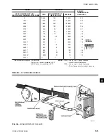
Страница 136: ...YORK INTERNATIONAL 136 FORM 160 55 O1 920 Operational Maintenance LD00470 FIG 61 ASSEMBLY OF DEHYDRATOR...
Страница 155: ...FORM 160 55 O1 920 155 YORK INTERNATIONAL NOTES...

