


14
JOHNSON CONTROLS
FORM 155.19-EG3 (1011)
A CPVC or fiberglass discharge pipe should run from the
rupture disk to a drain. Steel is not recommended unless
extra care is taken to support piping and isolate any stress
from the rupture disk. The discharge pipe must sup port
independent of the Two-Stage unit.
SOUND AND VIBRATION CONSIDERATIONS
Since the YPC unit generates very little vibration, vibration
eliminating mounts are not usually required. However,
when the machine is installed where even mild noise is
a problem, mounts or pads should be used (see Fig. 2,
p. 13). The use of anchoring bolts on the machine legs is
not normally necessary.
THERMAL INSULATION
YPC units require thermal insulation (by others) on both
hot and cold surfaces in order to achieve maximum ef
-
ficiency and prevent sweating. Required insulation area
is tabulated on page 17.
STEAM
General
– The YPC unit is nominally rated for dry steam
with minimal superheat, and a pressure of 115 PSIG (7.93
bar) (at the steam valve). The inlet steam must not have a
temperature higher than 363°F (183.9°C) and cannot have
a saturation pressure higher than 128 PSIG (8.83 bar).
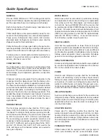
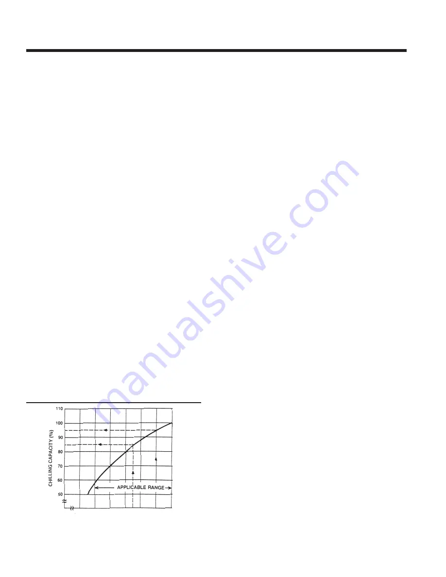
Pressure
– Since a lower steam saturation pressure
corresponds to a lower temperature in the generator, a
YPC chiller’s available capacity varies with the steam
pressures at the steam valve. Fig. 3 on p. 14 graphically
depicts the relationship between steam saturation pres
-
sure and available capacity.
Piping – The steam piping must follow the diagram found
in Fig. 4 on p. 15. Beginning at the steam supply, a steam
separator should be installed to ensure the unit receives
only dry steam. A steam trap below the separator will allow
draining of only condensate. Beyond the separator, a #50
mesh strainer removes foreign matter from the steam. A
regulator is only necessary if the steam supply pressure
to the unit will exceed 128 PSIG (8.8 bar). The pressure
relief valve should be set to open at 128 PSIG (8.83 bar).
The Johnson Controls-supplied steam control valve must
be no further than 200 inches (5 m) from the first-stage
generator steam inlet flange in order to minimize the
pressure drop from the valve exit to the generator inlet.
Dimension H1 is specified to prevent condensate back-
flow from the generator into the steam piping. Dimen sion
H2 is specified to prevent excessive backpressure to the
drain cooler. During factory testing, the unit is calibrated to
provide design condensate flow to a con densate system
operating at 15.0 PSIG (1 bar) (as measured immediately
downstream of the Drain Solenoid Valve). To duplicate this
condition in the field, an adjustable Condensate System
Backpressure Valve (by others) must be installed such
that:
∆PH2 + ∆P ∆PVALVE = 15.0 PSIG (1 bar)
Where:
∆PH2 = Pressure drop due to height, H2
∆PPIPING = Pressure drop due to condensate piping,
elbows, bends, etc.
∆PVALVE = Pressure drop due to Condensate Sys-
tem Backpressure Valve
The drain cooler installed on the unit effectively elimi nates
the need for an additional condensate cooler or a steam
trap. The drain solenoid valve is a factory in stalled device
to insure zero steam flow through unit during shutdown.
All steam piping should be adequately supported and
braced independent of the Two-Stage chiller. The sup port
system must account for the expansion and con traction
of steam piping, avoiding the imposition of strain on the
chiller components.
Control Valve Sizing – Control valves are sized for each
job based upon the available steam pressure, required
steam pressure at the unit, and the full load required
steam flow. During start-up, Johnson Controls technicians
estab lish the minimum load steam valve position (20%)
and set the limit switch accordingly, eliminating possible
problems at start up.
ELECTRICAL DATA
Table 2 contains unit electrical data. Total kW includes
power requirements for the system solution and refrig erant
pumps. All models have one solution pump, one solution
Application Data ‑ continued
FIG. 3 –
CAPACITY VS. INLET STEAM PRESSURE
AVAILABLE
PSIG
28.6 42.9 57.2 71.5 85.8 100 115
bar 1.97 2.96 3.94 4.93 5.92 6.90 7.93
STEAM INLET PRESSURE


