


FORM 155.19-EG3 (1011)
13
JOHNSON CONTROLS
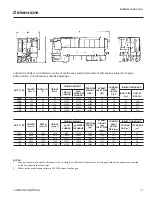
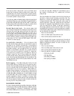
FIG. 2 –
TYPICAL NOISE AND VIBRATION LEVELS
NOISE LEVEL
VIBRATION LEVEL
whether they directly control the pumps or they are used
as inputs that tell the building automation system when
to supply flow. Absorption chillers require flow at shut
-
down to perform a dilution cycle that will vary in length
depending on operating conditions at shutdown. Without
flow, the dilution cycle will terminate early, which can lead
to crystallization.
Chilled Water
– The chilled water circuit should be de
-
signed for constant flow. A flow switch, provided standard
with the unit, must be installed in the chilled water line of
every unit. The switch must be located in the horizontal
piping close to the unit, where the straight horizontal
runs on each side of the flow switch are at least five pipe
diameters in length. The switch must be electrically con
-
nected to the chilled water interlock po sition in the unit
control center. A water strainer, of maximum 1/8” mesh
should be field-installed in the chilled water inlet line as
close as possible to the chiller. If located close enough
to the chiller, the chilled water pump may be protected
by the same strainer. The flow switch and strainer assure
chilled water flow during unit operation. The loss or severe
reduction of water flow could seriously impair the YPC unit
performance or even result in tube freeze-up.
Condenser Water
– Like the chilled water circuit, the
tower water circuit requires a means of proving flow. The
recommended method of proving flow is a tower water flow
switch (not in standard supply scope, but available from
Johnson Controls) installed in the tower water piping in the
same manner as the chilled water flow switch (above).
The YPC chiller is engineered for maximum effi ciency at
both design and part load operation by taking advantage
of the colder cooling tower water tempera tures which
naturally occur in the winter months. In its standard con
-
figuration, YPC absorbers can toler ate entering tower
water temperatures as low as 68°F (20°C). Because the
unit flow rates must be maintained, the recommended
method of tower water temperature con trol is a three way
mixing valve.
At the initial startup, entering tower water temperature may
be as low as 59°F (15°C), provided the water temperature
rises to 68°F (20°C) within twenty minutes.
LOW LEAVING CHILLED WATER ON/OFF CYCLING
Once the chiller reaches its minimum operating load, if the
cooling load decreases, the leaving chilled water tempera
-
ture will fall below the setpoint. When the leaving chilled
water temperature falls 3°F (1.7°C) below the setpoint,
the chiller will cycle off. During a cycling shutdown the
micropanel continues to monitor the leaving chilled water
temperature; when that temperature rises 1°F (0.55°C)
above the setpoint the chiller will cycle on. The on/off
cycling band used causes no noticeable effect for most
cooling applications. To prevent wear damage associated
with starting and stopping, it is recommended that instal
-
lations be designed to prevent the two-stage absorption
chiller from cycling more than twice per hour.
RUPTURE DISK PIPING
All YPC chillers ship with a rupture disk(s) de signed to fail
at 12 PSIG (0.83 bar). The purpose of the rupture disk is
to quickly relieve excess pressures as a precaution in the
event of an emergency such as a fire. All models have 4”
(101.6 mm) rupture disks (large tonnage units may have
more than one rupture disk, refer to factory submittal).


