background image

YORK INTERNATIONAL

73

FORM 150.64-EG1

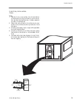
Typical Piping for Brazed-Plate

Coolers


Notes:

1.   Placement on a level surface free of obstructions 

(including snow, for winter operation) or air recircula-

tion ensures rated performance, reliable operation 

and ease of maintenance.

2.   Piping and wiring shown is for reference use only 

and is not in accordance with any national or local 

standards.

3.   All wiring and piping must comply with applicable 

local and national codes.

4.   All  wiring  and  piping  must  follow  standard  piping 

techniques  as  discussed  in  the ASHRAE  hand-

book.

5.   A strainer with a mesh size between .5 and 1.5 mm 

is recommended upstream of the heat exchanger to 

prevent clogging.

Pressure

Gauge

INLET

OUTLET

Drain

Vibration

Eliminators

Vibration

Eliminators

Shut Off

Valves

Strainer

Vent

Flow

Switch

Isolation

Valves

Содержание YCAL0041

Страница 1: ...FORM 150 64 EG1 505 AIR COOLED SCROLL CHILLERS STYLE D YCAL0041 YCAL0065 50 AND 60HZ 47 60 TON 165 210 KW R 22...

Страница 2: ...nglish Units 28 Part Load Ratings R 22 SI 29 Physical Data 30 Sound Data 32 Dimensions YCAL0041 English 34 Dimensions YCAL0045 English 36 Dimensions YCAL0051 English 38 Dimensions YCAL0055EC English 4...

Страница 3: ...g central station air handling or terminal units They are completely self contained and are designed for outdoor roof or ground level installation Each unit includes hermetic scroll compressors a liqu...

Страница 4: ...uipped with a heater controlled by a separate thermostat The heater provides freeze protec tion for the cooler down to 20 F 29 C ambient The cooler is covered with 3 4 19mm exible closed cell foam ins...

Страница 5: ...quid temperature cutout Low suction pressure cutout High discharge pressure cutout Anti recycle timer compressor start cycle time Anti coincident timer delay compressor starts UNIT section to Set time...

Страница 6: ...inate chiller failure due to AC powered failure battery discharge Programmed setpoints are retained in lithium battery backed RTC memory for 5 years minimum POWER PANEL Each panel contains Compressor...

Страница 7: ...ENT KIT HIGH Required if units are to operate when the ambient temperature is above 115 F 46 C Includes discharge pressure transducers This option includes the Discharge Pressure Transducer Readout Ca...

Страница 8: ...DX COOLER A split system arrangement with the cooler leaving return water sensors liquid line solenoid valves lter driers sightglasses TXVs shipped loose for eld connection to the air cooled con dens...

Страница 9: ...ic sound blanket The sound blankets are made with one layer of acoustical absorbent textile ber of 5 8 15mm thickness one layer of anti vibrating heavy material thickness of 1 8 3mm Both are closed by...

Страница 10: ...YORK INTERNATIONAL 10 This page intentionally left blank...

Страница 11: ...Liquid Temperatures 3 Outside ambient air temperature in degrees F 4 GPM of chilled liquid Determine capacity requirements from the following formula GPM TR x 24 RANGE F EXAMPLE WATER CHILLING 1 Give...

Страница 12: ...Correction Factors for 0 00025 fouling factor and 4 000 ft altitude READ 0 975 Tons factor 1 012 kW factor 5 From RATINGS on page 16 SELECT YCAL0045 English Units 35 3 Tons 41 1 Compressor kW 6 Deter...

Страница 13: ...065 models only 5 For operation at temperatures above 115 F 46 1 C the optional High Ambient Kit will need to be installed on the system Design Parameters ENGLISH YCAL LEAVING WATER TEMPERATURE F COOL...

Страница 14: ...Water Pressure Drop Note Water Pressure Drop Curves may extend past the minimum and maximum water ow ranges See page 13 for minimum and maximum ow points ENGLISH 1 10 100 10 100 1000 FLOW GPM Press D...

Страница 15: ...NAL 15 FORM 150 64 EG1 Note Water Pressure Drop Curves may extend past the minimum and maximum water ow ranges See page 13 for minimum and maximum ow points SI 1 10 100 1000 1 10 100 FLOW L S Press Dr...

Страница 16: ...S KW EER TONS KW EER TONS KW EER TONS KW EER TONS KW EER TONS KW EER 40 0 39 0 33 4 12 0 38 1 35 1 11 2 37 2 37 0 10 5 36 3 39 0 9 8 35 4 41 2 9 1 34 4 43 5 8 4 42 0 40 3 33 7 12 3 39 3 35 4 11 5 38 4...

Страница 17: ...RATURE ON CONDENSER F LCWT F 105 110 0 115 0 120 0 125 0 TONS KW EER TONS KW EER TONS KW EER TONS KW EER TONS KW EER 40 0 33 5 45 9 7 8 32 5 48 6 7 2 31 5 51 4 6 6 30 4 54 4 6 1 29 3 57 5 5 6 42 0 34...

Страница 18: ...0 95 0 100 0 TONS KW EER TONS KW EER TONS KW EER TONS KW EER TONS KW EER TONS KW EER 40 0 56 8 49 8 12 1 55 6 52 6 11 3 54 5 55 5 10 5 53 3 58 7 9 8 52 0 62 0 9 1 50 8 65 5 8 4 42 0 58 7 50 2 12 4 57...

Страница 19: ...RATURE ON CONDENSER F LCWT F 105 110 0 115 0 120 0 125 0 TONS KW EER TONS KW EER TONS KW EER TONS KW EER TONS KW EER 40 0 49 5 69 2 7 8 48 2 73 1 7 2 46 8 77 2 6 7 45 4 81 5 6 2 34 7 63 9 5 9 42 0 51...

Страница 20: ...KW KW COP KW KW COP KW KW COP KW KW COP KW KW COP 5 0 138 1 34 2 3 5 132 3 37 5 3 1 126 4 41 3 2 7 120 4 45 6 2 4 114 1 50 4 2 0 107 3 55 8 1 8 6 0 142 1 34 5 3 6 136 2 37 8 3 1 130 2 41 6 2 8 124 1...

Страница 21: ...COP KW KW COP KW KW COP KW KW COP KW KW COP 5 0 201 3 51 1 3 5 193 8 56 4 3 1 186 0 62 2 2 7 177 8 68 7 2 4 169 3 75 8 2 1 160 3 83 6 1 8 6 0 207 2 51 5 3 6 199 6 56 8 3 1 191 6 62 6 2 8 183 2 69 2 2...

Страница 22: ...EER TONS KW EER TONS KW EER TONS KW EER TONS KW EER TONS KW EER 40 0 32 9 25 9 13 6 32 2 27 5 12 6 31 5 29 2 11 7 30 8 31 0 10 8 30 0 32 9 10 0 29 2 35 0 9 2 42 0 34 0 26 2 13 9 33 3 27 8 12 9 32 6 2...

Страница 23: ...RATURE ON CONDENSER F LCWT F 105 110 0 115 0 120 0 125 0 TONS KW EER TONS KW EER TONS KW EER TONS KW EER TONS KW EER 28 4 40 0 37 3 8 4 27 6 39 7 7 7 26 6 42 2 7 0 25 7 45 0 6 4 24 7 47 9 5 8 29 4 42...

Страница 24: ...KW EER TONS KW EER TONS KW EER TONS KW EER TONS KW EER TONS KW EER 40 0 48 0 40 0 13 1 47 0 42 3 12 2 46 0 44 8 11 3 45 0 47 5 10 5 44 0 50 3 9 8 43 0 53 3 9 0 42 0 49 6 40 3 13 5 48 6 42 6 12 5 47 6...

Страница 25: ...RATURE ON CONDENSER F LCWT F 105 110 0 115 0 120 0 125 0 TONS KW EER TONS KW EER TONS KW EER TONS KW EER TONS KW EER 41 9 40 0 56 5 8 3 40 7 59 9 7 7 39 5 63 5 7 0 38 2 67 3 6 4 36 8 71 3 5 9 43 3 42...

Страница 26: ...KW COP KW KW COP KW KW COP KW KW COP KW KW COP 5 0 116 7 26 7 3 9 112 2 29 7 3 4 107 4 33 1 3 0 102 2 36 9 2 6 96 7 41 3 2 2 90 6 46 3 1 8 6 0 120 2 26 9 4 0 115 6 29 9 3 5 110 7 33 3 3 0 105 4 37 1 2...

Страница 27: ...COP KW KW COP KW KW COP KW KW COP KW KW COP 5 0 170 1 41 1 3 8 163 9 45 5 3 3 157 4 50 5 2 9 150 5 56 0 2 5 143 0 62 2 2 2 134 7 69 0 1 9 6 0 175 2 41 3 3 9 168 8 45 8 3 4 162 2 50 7 3 0 155 1 56 3 2...

Страница 28: ...bient F UNIT EER 100 0 43 5 48 7 95 0 9 6 69 2 33 7 28 3 81 4 11 9 48 3 24 4 17 2 68 6 14 6 20 9 13 3 7 2 55 0 18 7 IPLV 14 4 EER YCAL0055 FULL LOAD DISPL TONS KW Ambient F UNIT EER 100 0 47 6 52 8 95...

Страница 29: ...Ambient C UNIT COP 100 0 153 1 48 7 35 0 2 8 69 2 118 5 28 3 27 5 3 5 48 3 85 7 17 2 20 3 4 3 20 9 46 8 7 2 12 8 5 5 IPLV 4 23 COP YCAL055 FULL LOAD DISPL KW Comp KW Ambient C UNIT COP 100 0 167 3 52...

Страница 30: ...60 55 2 3 2 2 4097 4703 4142 4748 20 20 15 15 YCAL Model No Dimension General Unit Data Nominal Compressor Capacity Length Width Height Nomi nal KW R 22 Num ber of Refrig erant Circuits Refrigerant C...

Страница 31: ...300 3 Condenser Condenser Fans Low Sound Condenser Fans Ultra Quiet Evaporator Total Face Area m2 Number of Rows Fins per cm Number of Fans Fan Power kw fan Fan RPM Total Chiller fpm Number of Fans F...

Страница 32: ...73 91 YCAL0055 93 95 95 93 89 84 80 76 94 YCAL0061 93 95 95 93 89 84 80 76 94 YCAL0065 94 94 95 93 89 84 80 75 94 60Hz Line Frequency Ultra Quiet Fan R 22 63 125 250 500 1000 2000 4000 8000 dBA YCAL0...

Страница 33: ...73 69 88 YCAL0055 89 92 92 89 85 80 76 72 90 YCAL0061 90 91 91 89 85 80 76 72 90 YCAL0065 90 91 91 89 85 80 77 72 90 50Hz Line Frequency Ultra Quiet Fan R 22 63 125 250 500 1000 2000 4000 8000 dBA YCA...

Страница 34: ...ver the system designer must consider potential performance degradation Recommended minimum clearances front to wall 6 rear to wall 6 cooler end to wall 4 0 coil end to wall 6 top no obstructions allo...

Страница 35: ...5 16 Y C G X 1 1 16 ORIGIN END CAP WIDTH 21 13 16 TOP VIEW 9 13 16 1 1 16 9 13 16 9 16 DIA MOUNTING HOLES typ 144 13 16 15 1 16 13 15 16 TWO LIFTING HOLES BOTH SIDES FRONT VIEW C G X Z 38 5 5 16 25 3...

Страница 36: ...performance reli able operation and ease of maintenance Site restrictions may compromise minimum clearances indicated below resulting in unpredictable air ow patterns and possible diminished performa...

Страница 37: ...5 5 16 Y C G X 1 1 16 ORIGIN END CAP WIDTH 20 1 16 TOP VIEW 9 13 16 1 1 16 9 13 16 9 16 DIA MOUNTING HOLES typ 144 13 16 15 1 16 13 15 16 TWO LIFTING HOLES BOTH SIDES FRONT VIEW C G X Z 38 5 5 16 25 3...

Страница 38: ...performance reli able operation and ease of maintenance Site restrictions may compromise minimum clearances indicated below resulting in unpredictable air ow patterns and possible diminished performa...

Страница 39: ...5 5 16 Y C G X 1 1 16 ORIGIN END CAP WIDTH 20 1 16 TOP VIEW 9 13 16 1 1 16 9 13 16 9 16 DIA MOUNTING HOLES typ 144 13 16 15 1 16 13 15 16 TWO LIFTING HOLES BOTH SIDES FRONT VIEW C G X Z 38 5 5 16 25 3...

Страница 40: ...d performance reli able operation and ease of maintenance Site restrictions may compromise minimum clearances indicated below resulting in unpredictable air ow patterns and possible diminished perform...

Страница 41: ...45 5 16 Y C G X 1 1 16 ORIGIN END CAP WIDTH 18 7 16 TOP VIEW 9 13 16 1 1 16 9 13 16 9 16 DIA MOUNTING HOLES typ 144 13 16 15 1 16 14 TWO LIFTING HOLES BOTH SIDES FRONT VIEW C G X Z 38 5 3 16 25 3 8 2...

Страница 42: ...performance reli able operation and ease of maintenance Site restrictions may compromise minimum clearances indicated below resulting in unpredictable air ow patterns and possible diminished performa...

Страница 43: ...43 5 16 Y C G X 1 1 16 ORIGIN END CAP WIDTH 16 11 16 TOP VIEW 9 13 16 1 1 16 9 13 16 9 16 DIA MOUNTING HOLES typ 144 13 16 15 1 16 14 TWO LIFTING HOLES BOTH SIDES FRONT VIEW C G X Z 38 5 3 16 25 3 8...

Страница 44: ...performance reli able operation and ease of maintenance Site restrictions may compromise minimum clearances indicated below resulting in unpredictable air ow patterns and possible diminished performa...

Страница 45: ...6 43 5 16 16 11 16 38 5 3 16 153 5 8 15 1 16 16 25 3 8 28 9 16 CONTROL PANEL TWO LIFTING HOLES BOTH SIDES Y TOP VIEW C G X FRONT VIEW C G X Z 1 1 16 1 1 16 ORIGIN 9 13 16 9 13 16 B B 9 16 DIA MOUNTING...

Страница 46: ...l performance degradation Recommended minimum clearances front to wall 2m rear to wall 2m cooler end to wall 1 2m coil end to wall 2m top no obstructions allowed distance between adjacent units 3m No...

Страница 47: ...FORM 150 64 EG1 2301 1150 Y C G X 28 ORIGIN END CAP WIDTH 554 TOP VIEW 249 28 249 14 DIA MOUNTING HOLES typ 3678 383 355 TWO LIFTING HOLES BOTH SIDES FRONT VIEW C G X Z 965 135 645 346 B B COIL END CO...

Страница 48: ...intenance Site restrictions may compromise minimum clearances indicated below resulting in unpredictable air ow patterns and possible diminished performance YORK s unit controls will optimize operatio...

Страница 49: ...FORM 150 64 EG1 2301 1150 Y C G X 28 ORIGIN END CAP WIDTH 509 TOP VIEW 249 28 249 14 DIA MOUNTING HOLES typ 3678 383 355 TWO LIFTING HOLES BOTH SIDES FRONT VIEW C G X Z 965 135 645 346 B B COIL END CO...

Страница 50: ...intenance Site restrictions may compromise minimum clearances indicated below resulting in unpredictable air ow patterns and possible diminished performance YORK s unit controls will optimize operatio...

Страница 51: ...FORM 150 64 EG1 2301 1150 Y C G X 28 ORIGIN END CAP WIDTH 509 TOP VIEW 249 28 249 14 DIA MOUNTING HOLES typ 3678 383 355 TWO LIFTING HOLES BOTH SIDES FRONT VIEW C G X Z 965 135 645 346 B B COIL END CO...

Страница 52: ...intenance Site restrictions may compromise minimum clearances indicated below resulting in unpredictable air ow patterns and possible diminished performance YORK s unit controls will optimize operatio...

Страница 53: ...FORM 150 64 EG1 2301 1151 Y C G X 28 ORIGIN END CAP WIDTH 468 TOP VIEW 249 28 249 14 DIA MOUNTING HOLES typ 3678 383 356 TWO LIFTING HOLES BOTH SIDES FRONT VIEW C G X Z 965 131 645 726 B B COIL END CO...

Страница 54: ...intenance Site restrictions may compromise minimum clearances indicated below resulting in unpredictable air ow patterns and possible diminished performance YORK s unit controls will optimize operatio...

Страница 55: ...50 64 EG1 2301 1100 Y C G X 28 ORIGIN END CAP WIDTH 424 TOP VIEW R1 249 28 R2 249 L1 L2 14 DIA MOUNTING HOLES typ 3678 383 356 TWO LIFTING HOLES BOTH SIDES FRONT VIEW C G X Z 965 131 645 726 B B COIL...

Страница 56: ...intenance Site restrictions may compromise minimum clearances indicated below resulting in unpredictable air ow patterns and possible diminished performance YORK s unit controls will optimize operatio...

Страница 57: ...50 64 EG1 2301 1100 Y C G X 28 ORIGIN END CAP WIDTH 424 TOP VIEW R1 249 28 R2 249 L1 L2 14 DIA MOUNTING HOLES typ 3678 383 356 TWO LIFTING HOLES BOTH SIDES FRONT VIEW C G X Z 965 131 645 726 B B COIL...

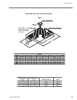
Страница 58: ...332 kg CIP C Red w Green CIP X ONE INCH DEFLECTION SPRING ISOLATOR CROSS REFERENCE Illustration shows single spring CIP B or CIP C mount HCL SBC Slot Width SW HCW MAX BOLT DIA MBD BASE PLATE DIMENSION...

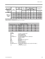
Страница 59: ...late Top Bottom Neoprene covered to prevent corrosion L T H W D ENGLISH Size D H L T W BC CS MBD ND C 2 9 16 2 3 4 5 1 2 1 4 2 5 16 4 1 80 1 2 13 x 1 1 2 ND D 3 3 8 2 3 4 6 1 4 5 16 4 5 1 2 13 x 1 1 2...

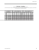
Страница 60: ...lbs 335 to 471 kg SLRS 2 C2 Green 1038 to 1497 lbs 471 to 679 kg SLRS 2 C2 Gray 1497 to 2058 lbs 679 to 933 kg SLRS 2 C2 Silver 2058 to 2619 lbs 933 to 1188 kg SLRS 2 C2 Gray w red 2619 to 3180 lbs 1...

Страница 61: ...YORK INTERNATIONAL 61 FORM 150 64 EG1 INTENTIONALLY LEFT BLANK...

Страница 62: ...r N E C Article 440 22 5 Circuit breakers must be UL listed and CSA certi ed and maximum size is based on 225 of the rated load amps for the largest motor plus 100 of the rated load amps for all other...

Страница 63: ...IT POWER MIN MAX 17 200 3 60 180 220 28 230 3 60 207 253 40 380 415 3 60 342 440 46 460 3 60 414 506 50 380 415 3 50 342 440 58 575 3 60 517 633 UNIT VOLTAGE UNIT VOLTAGE CONTROL POWER MCA NOTE A OVER...

Страница 64: ...MCM 1 6awg 350MCM 575 71 100 80 80 80 80 1 6awg 500MCM 1 6awg 350MCM 0051 200 228 250 250 250 250 250 1 6awg 500MCM 2 3 0 250MCM 230 212 250 225 250 225 250 1 6awg 500MCM 2 3 0 250MCM 380 123 150 150...

Страница 65: ...0 14 1 100 2 2 9 13 8 100 13 8 100 2 2 9 2 3 0 250MCM 40 0 350 40 0 350 2 7 6 49 4 316 53 8 374 2 7 6 2 3 0 250MCM 37 0 350 37 0 350 2 7 4 45 8 316 49 8 374 2 7 4 1 6awg 350MCM 21 3 195 21 3 195 2 4 5...

Страница 66: ...100 1 6awg 500MCM 1 6awg 350MCM 0051 380 415 103 150 110 110 110 110 1 6awg 500MCM 1 6awg 350MCM 0055 380 415 113 150 125 125 125 125 1 6awg 500MCM 1 6awg 350MCM 0061 380 415 124 150 150 150 150 150 1...

Страница 67: ...6 125 17 6 125 2 4 17 2 125 17 2 125 2 4 1 6awg 350MCM 17 6 158 17 6 158 2 4 21 8 127 23 7 187 2 4 1 6awg 350MCM 23 7 187 21 8 127 2 4 21 8 127 23 7 187 2 4 1 6awg 350MCM 30 1 225 23 7 198 2 4 23 7 16...

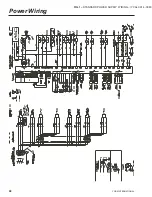
Страница 68: ...YORK INTERNATIONAL 68 Power Wiring FIG 1 STANDARD POWER SUPPLY WIRING YCAL 0014 0080...

Страница 69: ...YORK INTERNATIONAL 69 FORM 150 64 EG1...

Страница 70: ...YORK INTERNATIONAL 70...

Страница 71: ...YORK INTERNATIONAL 71 FORM 150 64 EG1 CTB1 21 13 20 13 14 13 FLOW SW REMOTE START STOP PWM INPUT LOAD LIMIT INPUT Factory wired with optional transformer Control Wiring LD03611...

Страница 72: ...g contractor or architect for special installation requirements Roof installations should incorporate the use of spring type isolators to minimize the transmission of vibration into the building struc...

Страница 73: ...e use only and is not in accordance with any national or local standards 3 All wiring and piping must comply with applicable local and national codes 4 All wiring and piping must follow standard pipin...

Страница 74: ...ar from date of initial start up or eighteen 18 months from date of shipment whichever occurs rst 1 03 DELIVERY AND HANDLING A Unit shall be delivered to job site fully assembled and charged with refr...

Страница 75: ...an integral part of condenser Design working pressure shall be 450 PSIG 31 bar 2 Low Noise Fans Shall be dynamically and statically bal anced direct drive corrosion re sistant glass ber reinforced com...

Страница 76: ...dis charge pressure and low suction pressure D Manufacturer shall provide any controls not listed above necessary for automatic chiller operation Mechanical Contractor shall provide eld control wiring...

Страница 77: ...per Fin Provide copper ns in lieu of alumi num 3 Post Coated Dipped Dipped cured coating on condenser coils for seashore and other corro sive applications with the exception of strong alkalis oxidizer...

Страница 78: ...trol Panel Field mounted Graphical interface panel to remotely control and monitor up to 8 different units W Multi Unit Sequencing Panel Field mounted Separate Sequencing control center is provided to...

Страница 79: ...YORK INTERNATIONAL 79 FORM 150 64 EG1...

Страница 80: ...O Box 1592 York Pennsylvania USA 17405 1592 Copyright by York International Corporation 2004 Subject to change without notice Printed in the USA Form 150 62 EG1 103 Supersedes 150 62 EG1 102 RPC 3M 3...

Отзывы: