JOHNSON CONTROLS
33
FORM 160.00-O2
ISSUE DATE: 04/30/2019
7
SECTION 7 – START-UP INSTRUCTIONS
START-UP CHECKLIST
•
IMPORTANT
- Remove all debris from the
starter cabinet where AC powerline cables at-
tach to starter bus bars. This includes nuts, bolts,
washers, hand tools, test equipment, metal shav-
ings etc. Motor starting current creates strong
magnetic fields that can pull metal objects into the
starter bus bars possibly causing short circuits,
and damaging the Solid State Starter!!
•
Drain and fill the SCR heatsink assembly cool
-
ing loop with coolant (refer to Fill Cooling Loop
section).
• Connect wiring to the starter per the proper wir-
ing diagram.
• If the LCSSS is intended for generator operation,
and the Logic/Trigger Board is a Rev. C or earlier,
the JP1 jumper must be cut. If the LCSSS is intend-
ed for generator operation, and the Logic/Trigger
Board is a Rev. D or later no jumpers need to be cut.
(Refer to
for location of
JP1)
• Apply power to the chiller and the LCSSS.
• On the OptiView Control Center, verify the fol-
lowing have been properly entered: (Refer to AS-
SOCIATED LITERATURE for Opti-View Con-
trol Center Operation Instruction form for your
chiller type on page 3 of this form).
A. Local motor current limit setpoint
B. Pulldown demand limit
C. Chiller full load amps setpoint.
D. Supply voltage range setpoint.
E. Chiller starting amps setpoint.
F. KWH Reset
• The LCSSS is now ready to start the chiller.
FILL COOLING LOOP
The following procedure details the method of filling
the cooling loop. The Style B LCSSS is shipped with
a 50/50 mix of Propylene Glycol and YORK Corro-
sion Inhibitor. This type of coolant is being used to
protect the cooling loop from damage due to freezing
conditions during the shipping process. This coolant
mixture does not have the thermodynamic properties
required by the LCSSS during a running condition.
Thus, this 50/50 mixture must be drained and replaced
with YORK coolant as currently used in the LCSSS.
Propylene Glycol is the same material used to winter-
ize recreational vehicles. Although it is non-toxic fol-
low local guidelines for proper disposal.
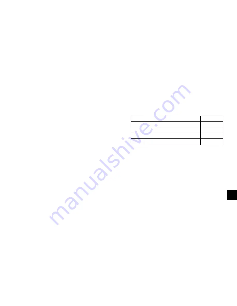
TABLE 9 -
REQUIRED MATERIAL
ITEM
DESCRIPTION
QUANTITY
1
Funnel wide mouth
1 EA.
2
Bucket one gallon
1 EA.
3
Gallon container of YORK Coolant
1 EA.
4
Teflon tape
Drain Procedure
1. Assemble the material listed above.
2. Remove the plastic pipe plug from the top of the
coolant reservoir. Be sure to hold the coolant res-
ervoir when removing the pipe plug.
3. Position the bucket under the drain cap. The drain
cap is located below the coolant pump on the heat
exchanger.
4. Remove the drain cap, capture the 50/50 mixture
and discard the used coolant as suggested above.
Do not reuse coolant. Remove J2, J3, J4 tempo-
rarily. The coolant pump will turn on to remove
the rest of the coolant from the system.
5. After most of the 50/50 mixture has been drained,
wrap the drain cap with Teflon tape, and replace
the drain cap. Do not over-tighten the cap.
Содержание SSS 14L-B
Страница 4: ...JOHNSON CONTROLS 4 FORM 160 00 O2 ISSUE DATE 04 30 2019 THIS PAGE INTENTIONALLY LEFT BLANK...
Страница 8: ...JOHNSON CONTROLS 8 FORM 160 00 O2 ISSUE DATE 04 30 2019 THIS PAGE INTENTIONALLY LEFT BLANK...
Страница 24: ...JOHNSON CONTROLS 24 FORM 160 00 O2 ISSUE DATE 04 30 2019 THIS PAGE INTENTIONALLY LEFT BLANK...
Страница 30: ...JOHNSON CONTROLS 30 FORM 160 00 O2 ISSUE DATE 04 30 2019 THIS PAGE INTENTIONALLY LEFT BLANK...


