background image

987158-UIM-B-1013

18

Johnson Controls Unitary Products

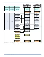
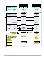
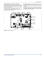
 FIGURE 25:  

Thermostat Chart - Single Stage Heat Pump – Variable Speed or PSC Modulating Furnace

C

24 – Volt Common

R

24 – Volt Hot

Y1

First Stage Compressor

O

Reversing Valve

Energized in Cool

L

Malfunction Light

G

Fan

*DP32H70124

THERMOSTAT

W1

Second Stage Aux. Heat

E

Emergency Heat

W2

Third Stage Heat

Step 1 of Thermostat

Installer / Configuration

Menu must be set to

Heat Pump 1

C

24 – Volt Common

R

24 – Volt Hot

Y1

First Stage Compressor

O

Reversing Valve

Energized in Cool

L

Malfunction Light

Y2

Second

Stage Compressor

G

Fan

*BP21H50124

*BN21H00124

*DP21H40124

*DN21H00124

THERMOSTAT

E

Emergency Heat

W2

Second Stage Heat

B/O Switch on Thermostat

must be in the O position

C

24 – Volt Common

Y1

First Stage Compressor

O/B

Reversing Valve

L

Malfunction Light

Y2

Second

Stage Compressor

G

Fan

*DN22U00124

THERMOSTAT

E

Emergency Heat

AUX

Auxiliary Heat

R

24 – Volt Hot

(Heat XFMR)

R

24 – Volt Hot
(Cool XFMR)

O

Reversing Valve

Energized in Cool

C

24 – Volt Common

R

24 – Volt Hot

W1 OUT

First Stage Heat

W2 OUT

Second Stage Heat

Y2 OUT

Second

Stage Compressor

Y1

Single

Stage Compressor

X/L

Malfunction Light

Y2

Second

Stage Compressor

W

Auxiliary Heat

BS

Bonnet Sensor

BSG

Bonnet Sensor

YORKGUARD VI

CONTROL

SINGLE STAGE

HEAT PUMP

Bonnet Sensor

(Optional)

Change FFuel jumper

on the heat pump control

to “ON”

1

H*3

YMB

YZB

OD MODELS

Y2

Second

Stage Compressor

Thermostat Installer Setup

1-System Type-must be set

 to 5 – 2 Heat/1 Heat Pump

Thermostat Installer Setup

2-Changeover Valve-must

be set to 0 – O/B terminal 

Energized in Cooling

C

24 – Volt Common

R

24 – Volt Hot

Y1

Single

Stage Compressor

MODULATING

FURNACE CONTROL

G

Fan

MODULATING

FURNACE

Y/Y2

Second or Full

Stage Compressor

DHUM

Dehumidification-

Open on Humidity Rise

W

Modulating Heat

 Part Numbers:

SAP   =    Legacy         

2

2

Move HUMIDISTAT

jumper to “YES”

if humidistat is to be used. 

ID MODELS

LO COMP

Single Stage 

Compressor (OUT)

O

Reversing Valve

Energized in Cool

HI COMP

Second Stage 

Compressor (OUT)

Change Hot Heat Pump 

jumper on the heat 

pump control to “ON” if 

Hot Heat Pump 

Operation is desired.

 Part Number:

S1-2HU16700124

3

External Humidistat

(Optional)

Open on Humidity Rise

3

Part Numbers:

SAP   =    Legacy

126768 = 031-09137

18395   =  031-01996
340512 =  031-09178

1

TP9C

YP9C

CP9C

LP9C

H*6

YZF

Содержание CPLCC

Страница 1: ...and Duct Dimensions 9 Recommended Filter Sizes High Velocity 600 FPM 9 High Altitude Orifices 11 Ratings Physical Electrical Data 11 Estimated Free Area 21 Unconfined Space Minimum Area 21 Free Area 21 Gas Rate CU FT HR at Full Input 25 Inlet Gas Pressure Range 26 Nominal Manifold Pressure 26 Blower Performance CFM Any Position 28 These high efficiency compact units employ induced combustion reli ...

Страница 2: ...support the ends of the furnace rather than lifting by the cabinet flanges at the return air openings bottom or sides or supply air opening 13 When lifting the furnace it is acceptable to use the primary heat exchanger tubes as a lifting point provided that the tubes are lifted at the front of the heat exchangers where attached to the vestibule panel Do not use the top return bend of the heat exch...

Страница 3: ...t the National Fire Protection Association Inc Batterymarch Park Quincy MA 02269 or for only the NFGC contact the American Gas Association 400 N Capital N W Washington DC 20001 or www NFPA org CANADA NSCNGPIC For a copy contact Standard Sales CSA International 178 Rexdale Boulevard Etobicoke Toronto Ontario Canada M9W 1RS STEP 3 Combustion and Ventilation Air US Section 5 3 of the NFGC air for Com...

Страница 4: ...f the side wall horizontal vented gas fueled equipment the installing plumber or gasfitter shall observe that a hard wired carbon monoxide detector with an alarm and battery back up is installed on the floor level where the gas equipment is to be installed In addition the installing plumber or gasfitter shall observe that a battery operated or hard wired carbon monoxide detector with an alarm is i...

Страница 5: ...es are rotated down for shipment In order to use the flanges remove the screw holding an individual flange rotate the flange so it is in the upward position and reinstall the screw then repeat this for all 4 flanges If the flanges are not used they should remain in the rotated down posi tion as shipped DUCTWORK INSTALLATION AND SUPPLY PLENUM CONNECTION UPFLOW HORIZONTAL Attach the supply plenum to...

Страница 6: ...ides of the furnace and the building joists studs or framing This line may be in contact with combustible material Refer to Figure 4 When moving or handling this furnace prior to installation always leave the doors on the furnace to provide support and to prevent damage or warping of the cabinet When lifting the furnace support the ends of the furnace rather than lifting by the cabinet flanges at ...

Страница 7: ...exchang ers where attached to the vestibule panel Do not use the top return bend of the heat exchangers as lifting points as the tubes may shift out of position or their location brackets baffles DOWNFLOW APPLICATION To apply the furnace in a downflow position it will be necessary to rotate the vent blower 90 left or right so that the vent pipe passes through the side of the furnace casing rather ...

Страница 8: ...e 2 COIL FURNACE ASSEMBLY HC SERIES COILS These coils are supplied ready to be installed in a right hand position or a left hand position When used in conjunction with a horizontal furnace blow through application the coil should be oriented with the opening of the A coil closest to the furnace See Figure 12 FIGURE 8 Coil Flange FIGURE 9 Horizontal Right Application Typical FIGURE 10 Horizontal Le...

Страница 9: ...nal filter box FIGURE 13 Dimensions LEFT SIDE RIGHT SIDE 5 5 RETURN END B 24 25 29 5 For Cladded door add appoximately an additional 75 28 5 Electrical Entry Gas Pipe Entry Thermostat Wiring FRONT 14 1 1 5 23 SUPPLY END C 24 38 20 5 B Gas Pipe Entry Thermostat Wiring 33 A 5 Electrical Entry Vent Connection Outlet Vent Connection Outlet 4 Diameter Outlet Vent Connection Table 3 Cabinet and Duct Dim...

Страница 10: ... by 4 per 1 000 feet above sea level The modulating furnaces automatically de rate for altitude by measuring the inducer blower pressure and using that to determine if there is adequate air to support good combustion If there is not enough combustion air to properly support 100 of the furnace nameplate input rate the control will reduce the input to the point that there will be good combustion An ...

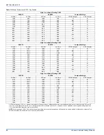
Страница 11: ...2 68 64 60 Orifice Drill Size 100 48 49 49 50 51 51 52 95 47 48 49 50 50 50 51 90 46 47 48 49 49 49 50 85 45 46 47 48 49 49 50 80 45 45 46 47 48 48 49 75 44 45 45 45 47 47 49 70 43 44 44 45 45 45 48 65 42 43 43 44 45 45 47 60 41 42 42 43 44 45 46 55 40 41 41 32 43 43 44 50 39 40 40 40 43 42 42 PROPANE KITS It is very important to choose the correct kit and or gas orifices for the altitude and the ...

Страница 12: ...communica tions control wiring see the section below entitled Control Wiring using Communicating Controls The Communicating System consists of several intelligent communicat ing components including the Communicating Thermostat Control touch screen wall thermostat modulating variable speed furnace air conditioner 15 and 18 SEER premium air conditioners or heat pump 13 15 and 18 SEER premium heat p...

Страница 13: ...through cabinet The 24 volt 40 VA transformer is sized for the furnace components only and should not be connected to power auxiliary devices such as humidifiers air cleaners etc The transformer may provide power for an air conditioning unit contactor AIR CONDITIONER CONNECTIONS This furnace may be used with single stage or two stage air condition ing units For Single Stage A C Connect the low vol...

Страница 14: ...r W914 for electric heat on thermostat is not necessary C 24 Volt Common Y Compressor SINGLE STAGE AIR CONDITIONER Y Compressor Contactor SINGLE STAGE AIR CONDITIONER C 24 Volt Common R 24 Volt Hot Y1 Single Stage Compressor MODULATING FURNACE CONTROL G Fan MODULATING FURNACE Y Y2 Second or Full Stage Compressor DHUM Dehumidification Open on Humidity Rise W Modulating Heat Part Numbers SAP Legacy ...

Страница 15: ...optional when used with batteries Thermostat Installer Setup 0170 System Type must be set to 8 2 Heat 2 Cool Multistage Conventional Connection of the C terminal 24 volt common is optional when used with batteries Thermostat Installer Setup 1 System Type must be set to 6 2 Heat 2 Cool Multistage Conventional Thermostat Installer Setup 15 Compressor Protection must be set to 5 C 24 Volt Common R 24...

Страница 16: ...on R 24 Volt Hot Y1 Single Stage Compressor MODULATING FURNACE CONTROL G Fan MODULATING FURNACE Y Y2 Second or Full Stage Compressor DHUM Dehumidification Open on Humidity Rise W Modulating Heat Part Numbers SAP Legacy 1 1 Move HUMIDISTAT jumper to YES if humidistat is to be used ID MODELS LO COMP Single Stage Compressor OUT O Reversing Valve Energized in Cool HI COMP Second Stage Compressor OUT T...

Страница 17: ...OL X L Malfunction Light W Auxiliary Heat SINGLE STAGE HEAT PUMP 1 1 Part Number S1 2HU16700124 3 Y2 Second Stage Compressor Step 9 of Thermostat Installer Configuration Menu must be set to Pump OFF Step 1 of Thermostat Installer Configuration Menu must be set to Heat Pump 1 OD MODELS HGD HJR C 24 Volt Common R 24 Volt Hot Y1 Single Stage Compressor MODULATING FURNACE CONTROL G Fan MODULATING FURN...

Страница 18: ...eat W2 OUT Second Stage Heat Y2 OUT Second Stage Compressor Y1 Single Stage Compressor X L Malfunction Light Y2 Second Stage Compressor W Auxiliary Heat BS Bonnet Sensor BSG Bonnet Sensor YORKGUARD VI CONTROL SINGLE STAGE HEAT PUMP Bonnet Sensor Optional Change FFuel jumper on the heat pump control to ON 1 H 3 YMB YZB OD MODELS Y2 Second Stage Compressor Thermostat Installer Setup 1 System Type mu...

Страница 19: ...rgency Heat R 24 Volt Hot Heat XFMR RC 24 Volt Hot Cool XFMR AUX Auxiliary Heat Step 1 of Thermostat Installer Configuration Menu must be set to HP2 Selection of GAS ELEC switch on thermostat not necessary Thermostat Installer Setup 0170 System Type must be set to 12 3 Heat 2 Heat Pump Thermostat Installer Setup 0190 Changeover Valve must be set to 0 O B terminal Energized in Cooling Thermostat In...

Страница 20: ...d to a 2 stage thermostat and a 2 stage heat pump 4 Hot Heat Pump The hot heat pump feature will not work when the control is wired to a single stage thermostat and a 2 stage heat pump TWINNING These furnaces are not to be twinned If more than one furnace is needed in an application each furnace must have its own complete duct system and its own wall thermostat SECTION VI VENT SYSTEM VENT CONNECTI...

Страница 21: ...creen shall have no dimen sion smaller than 0 25 0 64 cm 3 A manually operated damper or manually adjustable louvers are not permitted for use 4 A automatically operated damper or automatically adjustable louvers shall be interlocked so that the main burner cannot operate unless either the damper or the louver is in the fully open position FIGURE 28 Combustion Airflow Path Through The Furnace Casi...

Страница 22: ...ectional area as the free area of the air supply inlet opening to which it connects 4 The blocking effects of louvers grilles and screens must be given consideration in calculating free area If the free area of a specific louver or a grille is not known Refer to Table 7 to estimate free area Ventilated Combustion Air The ventilated attic space or a crawl space from which the combustion air is take...

Страница 23: ...iances connected to the venting system are not in operation 1 Inspect the venting system for proper size and horizontal pitch Determine that there is no blockage restriction leakage corrosion or other deficiencies which could cause an unsafe condition 2 Close all building doors and windows 3 Turn on clothes dryers and TURN ON any exhaust fans such as range hoods and bathroom exhausts so they shall...

Страница 24: ...r 1 Turn off all other gas appliances and pilots 2 Run furnace for a minimum of 3 minutes in heating operation 3 Measure time in sec for gas meter to complete 1 revolution and note reading The 2 cubic feet dial provides a more accurate mea surement of gas flow 4 Refer to Table 10 for cubic feet of gas per hour 5 Multiply cubic feet per hour by heating valve BTU cu ft to obtain input If clocked rat...

Страница 25: ...0 300 750 78 46 92 231 25 144 288 720 80 45 90 225 26 138 277 692 82 44 88 220 27 133 267 667 84 43 86 214 28 129 257 643 86 42 84 209 29 124 248 621 88 41 82 205 30 120 240 600 90 40 80 200 31 116 232 581 92 39 78 196 32 113 225 563 94 38 76 192 33 109 218 545 96 38 75 188 34 106 212 529 98 37 74 184 35 103 206 514 100 36 72 180 36 100 200 500 102 35 71 178 37 97 195 486 104 35 69 173 38 95 189 4...

Страница 26: ...hanging the ATR jumper on the furnace control board The jumper is factory set to deliver an air temperature rise near the midpoint of the nameplate temperature rise range If more air is desired lower temper ature rise move the jumper to the 10 position If less air is desired higher temperature rise move the jumper to the 10 position Table 11 Inlet Gas Pressure Range INLET GAS PRESSURE RANGE Natura...

Страница 27: ... adjustments to the cooling blower airflow Continuous Fan Operation The airflow delivered by the furnace dur ing continuous fan operation can be adjusted as desired This is done my moving the control fan jumper on the control board to give the desired airflow The jumper has three positions The H position delivers maximum air flow 100 of the blower capacity Position M delivers approximately 70 of t...

Страница 28: ... H B 1125 750 1065 660 MH B 1225 820 1165 720 H A 1050 680 960 600 MH A 1100 740 1050 590 H C 890 600 855 525 ML B 920 615 875 540 MH C 675 450 640 395 L B 815 545 775 495 ML A 600 440 580 380 L A 720 499 700 430 ML C 540 440 525 380 L C High Low Speed Cooling CFM 080C16 100C16 Jumper Settings Hi Cool Lo Cool Hi Cool Lo Cool COOL Jumper ADJ Jumper 1715 1165 1600 1120 H B 1520 1020 1450 980 MH B 15...

Страница 29: ...se controls are mounted on the burner assembly If the temperature in the burner area exceeds its set point the ignition control and the gas valve are de energized The operation of this control indicates a mal function in the combustion air blower heat exchanger or a blocked vent pipe connection Corrective action is required These are manual reset controls that must be reset before operation can co...

Страница 30: ...ith call for cooling Two Amber Flashes Normal operation with call for heat Three Amber flashes Normal operation burner is on at end of heat ing cycle after wall thermostat has been satisfied Four Amber Flashes Heating capacity is reduced due to restriction in the circulating air system Check for dirty filter or closed registers Five Amber Flashes Heating capacity is reduced due to restriction in t...

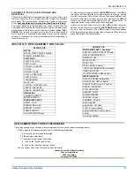
Страница 31: ...will flash three green flashes when the memory has been cleared then will resume the normal slow green flash after a five second pause SECTION X REPLACEMENT PARTS LIST DESCRIPTION MOTOR MOTOR DIRECT DRIVE BLOWER BLOWER COMBUSTION ELECTRICAL CAPACITOR RUN SWITCH LIMIT CONTROL FURNACE IGNITER SENSOR FLAME SWITCH PRESSURE SWITCH DOOR TRANSFORMER VALVE GAS CONTROL TEMPERATURE SENSOR PRESSURE SENSOR TH...

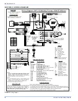
Страница 32: ... Condition None 1 Slow Green Rapid Amber 1 Amber 2 Amber 3 Amber 4 Amber 5 Amber 6 Amber Steady on Red 1 Red 2 Red 3 Red 4 Red 5 Red 6 Red 7 Red 8 Red 9 Red 10 Red 11 Red 12 Red SERVICING THIS UNIT OPEN ALL DISCONNECTS BEFORE CAUTION PRECAUTION OUVREZ LES DISJONCTEURS AVANT DE PROCEDER AVEC LE SERVICE DS ROS1 ROS2 XFMR HSI PF PS EAC LS HUM Legend Door Switch Roll Out Switch Roll Out Switch Transfo...

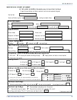
Страница 33: ...age value between R and C on furnace control board volts AC Thermostat Type Other System Equipment and Accessories Owner Information Equipment Data Furnace Configuration Venting B Vent Electrical Line Voltage Outdoor Unit Model Outdoor Unit Serial Filter Thermostat Accessories Filter Location s Connections All Per Installation Instructions and Local Code Gas piping is connected including drip leg ...

Страница 34: ...c before evaporator coil in w c Calculated input in btuh clock the gas meter Nat Gas Only Manifold Gas Pressure in w c furnace must be in TEST Mode for setup Inlet Gas Pressure in w c LP Gas Conversion Kit Part Used Burner flame inspected flames are blue and extending directly into the primary heat exchanger cells Return Static in w c after filter furnace side Air Side Heating Air Side Continuous ...

Отзывы: