


YORK INTERNATIONAL
7
FORM 160.49-O1
CONTROL CENTER
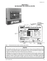
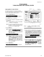
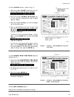
The Control Center front panel layout consists of five
key groups, one switch and a 1 line by 40 character al-
phanumeric vacuum fluorescent display: (see Fig. 3.)
CHARACTERISTIC DISPLAY – The alphanumeric
vacuum fluorescent display is located to the right of
the STATUS key. All messages, parameters, set points,
and data can be viewed at this location. The main com-
munications between the operator or service techni-
cian and the MicroComputer Control Center occurs on
this display.
DISPLAY – Provide a direct readout of each monitored
parameter on the alphanumeric display.
ENTRY – These keys are used to enter the values for
the operator programmed setpoints. These keys are
used in conjunction with the Setpoint keys while in
PROGRAM mode.
SETPOINTS – These keys are used as follows:
1. To view each setpoint, in any mode, or
2. To select the individual setpoints that are pro-
grammed by the operator in PROGRAM mode only.
Pressing the appropriate key enables the operator to
program that setpoint pressing the Entry keys.
SERVICE – Included in this group of keys are those
functions that are only relevant to servicing the chiller.
Typically, these keys would not be used for daily chiller
operation.
ACCESS CODE – Permits operator to access the pro-
gram.
PROGRAM – Permits operator to program the Control
Center.
MODE – Permits operator to check what mode the Con-
trol Center is presently in (LOCAL, REMOTE or SER-
VICE).
1. Service – allows manual PRV control with visual
display readout of PRV operation.
2. Local – allows manual compressor start from the
COMPRESSOR switch on the Control Center front.
3. Program – allows operator programming of system
setpoints.
4. Remote – allows remote start, remote stop of com-
pressor and remote reset of LCWT and % current
limit.
COMPRESSOR-START, RUN, STOP/RESET
SWITCH – This 3-position rocker switch is used to start
(except in REMOTE mode), stop/run/reset the system.
OPERATION
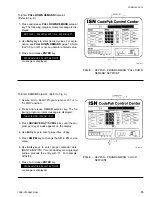
DISPLAYING SYSTEM PARAMETERS
The Display key are used to display selected moni-
tored parameters as follows: (Refer to Fig. 3.)
• Press and release the appropriate Display key –
the message will be displayed for 2 seconds.
– or –
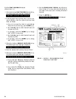
• Press and hold the appropriate Display key – the
message will be displayed and updated every 0.5
seconds until the Display key is released.
– or –
• Press and release appropriate Display key, then
press and release the DISPLAY HOLD key – the
message will be displayed and updated every 2 sec-
onds until the DISPLAY HOLD key is again pressed
and released, or 10 minutes have elapsed, which-
ever comes first.
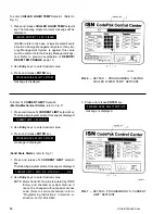
NOTE: If the display actually displays X’s, then the
monitored parameter is out of normal operat-
ing range (refer to Fig. 4). If the “English/Met-
ric” jumper is installed on the Micro Board, all
temperatures are displayed in degrees Fahr-
enheit (°F) and all pressures are displayed in
pounds per sq. inch gauge (PSIG) except oil
pressure which is displayed in pounds per sq.
inch differential (PSID). If the “English/Metric”
jumper is not installed, all temperatures are
displayed in degrees Centigrade (°C) and all
pressures are displayed in Kilo-Pascals (kPa).