


Y
ORK INTERNA
TIONAL
41
FORM 160.49-O1
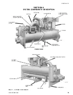
SECTION 6
T
R
OUBLESHOO
TING
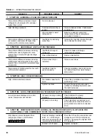
TABLE 1 – CAUSES OF NORMAL AND SAFETY SYSTEM SHUTDOWNS IN ACCORDANCE WITH THE MICROCOMPUTER CONTROL, CENTER DISPLAY
SHUTDOWN CAUSE
GOVERNING CONTROL FUNCTION
CONTROL CENTER DISPLAY
OPERATING
PROGRAMMED
START-UP OF
PROBABLE CAUSE
DAY OF
TIME OF
CAUSE OF
METHOD OF
DESCRIPTION
POINT
SETPOINTS
SYSTEM AFTER
AND SERVICE
WEEK
DAY
SHUTDOWN
RESTART
ON
ON
BY OPERATOR
SHUTDOWN
REQUIRED
RISE
FALL
MON.
10:00 AM
Low Water
Autostart
Low Water
Chilled
4°F (2.2°C)
4°F (2.2°C) be-
Automatic Restart
System load is less
Temp.
(LWT)
water
below
low chilled water
when water reaches
than minimum capacity
setpoint
chiller
setpoint (If set
setpoint; if system is
water
to 40°F (4.4°C)
running and setpoint
setpoint
would be 36°F
is increased 4°F, sys-
(2.2°C)) (36°F
tem will continue to
(2.2°C) mini-
run, as LWT cutout
mum)
shifts to a fixed 36°F
for 10 minutes.
MON.
10:00 AM
Flow Switch
Autostart
Flow Switch
Automatic Restart
Lack of water flow.
when water flow is
Check operation of
Restored to close
chilled water pump
flow switch.
MON.
10:00 AM
System
Autostart
A remote com-
Automatic Restart
Contact-connected to
Cycling
mand (computer
upon remote
the Remote/Local
relay contact or
command.
cycling input of the
manual switch)
Digital input board
MON.
10:00 AM
Multi-Unit
Autostart
(Optional) Lead-
Automatic Restart
Contact-connected to
Lag Sequence
upon remote
the Multi-Unit cycling
Control
command.
input of the Digital
input board
MON.
10:00 AM
Internal
Autostart
Internal Clock
Daily Schedule
Will automatically
Pressing Compressor
Clock
Programmed to
restart when pro-
Start Switch over-
Shutdown Unit
grammed schedule
rides the program
permits
MON.
10:00 AM
AC under-
Autostart
<15% FLA for
Cycling shutdown occurs
voltage
25 continuous
when motor current is
seconds
>15% FLA for 25 seconds
during chiller operation
MON.
10:00 AM
Power Fault
Autostart
CM-2 Current
Will start automatic-
Motor Controller contacts
Module or
tically following
opening and closing in
Solid State
coastdown
less than 3 seconds due to
Starter
a power fault condition
Remote Stop
Energy manage-
Start up by start
Remote Stop Contact
ment System
signal from remote
Closure
start switch
MON.
Anti-Recycle,
Anti-Recycle
Will not start
Will restart when
Min. Time between
20 Min. Left
timer
until 30 Min.
time left = 00 Min.
successive compres-
timer is timed
sor starts is 30 min.
MON.
10:00 AM
Low Evap.
Low Evap.
54..3 PSIG 54.4 PSIG
To restart press com-
See OPERATION
Pressure
Pressure
(374.4 kPa)
(375 kPa)
pressor switch from
ANALYSIS TABLE 2
Transducer
(R-22)
(R-22)
STOP/RESET to
Symptom 2.
(LEP)
25 PSIG
25.1 PSIG
START position.
(172.4 kPa)
(173 kPa)
(R-134a)
(R-134a)
(Continued on Page 42)


