background image

48

  YORK INTERNATIONAL

VACUUM TESTING

After the pressure test has been completed, the vacuum
test should be conducted as follows:

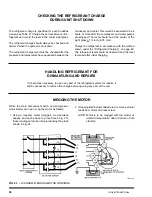
1. Connect a high capacity vacuum pump, with indi-

cator, to the system charging valve as shown in
Fig. 22 and start the pump. (See “Vacuum Dehydra-
tion”.)

2. Open wide all system valves, including the purge

and gauge valves. Be sure all valves to the atmo-
sphere are closed.

3. Operate the vacuum pump in accordance with

VACUUM DEHYDRATION until a wet bulb tempera-
ture of +32°F (0°C) or a pressure of 5 mm Hg is
reached. See Table 3 for corresponding values of
pressure.

4. To improve evacuation circulate hot water (not to

exceed 125°F, 51.7°C) through the cooler and con-
denser tubes to thoroughly dehydrate the shells. If
a source of hot water is not readily available, a
portable water heater should be employed. DO NOT
USE STEAM. A suggested method is to connect a
hose between the source of hot water under pres-
sure and the cooler head drain connection, out the
cooler vent connection, into the condenser head
drain and out the condenser vent. To avoid the pos-
sibility of causing leaks, the temperature should be
brought up slowly so that the tubes and shell are
heated evenly.

5. Close the system charging valve and the stop valve

between the vacuum indicator and the vacuum
pump. Then disconnect the vacuum pump leaving
the vacuum indicator in place.

6. Hold the vacuum obtained in Step 3 in the system

for 8 hours; the slightest rise in pressure indicates
a leak or the presence of moisture, or both. If, after
8 hours the wet bulb temperature in the vacuum
indicator has not risen above 40°F (4.4°C) or a pres-
sure of 6.3 mm Hg, the system may be considered
tight.


NOTE: Be sure the vacuum indicator is valved off

while holding the system vacuum and be
sure to open the valve between the vacuum
indicator and the system when checking
the vacuum after the 8 hour period.

7. If the vacuum does not hold for 8 hours within the

limits specified in Step 6 above, the leak must be
found and repaired.

VACUUM DEHYDRATION

To obtain a sufficiently dry system, the following in-
structions have been assembled to provide an effec-
tive method for evacuating and dehydrating a system
in the field. Although there are several methods of de-
hydrating a system, we are recommending the follow-
ing, as it produces one of the best results, and affords
a means of obtaining accurate readings as to the ex-
tent of dehydration.

The equipment required to follow this method of dehy-
dration consists of a wet bulb indicator or vacuum
gauge, a chart showing the relation between dew point
temperature and pressure in inches of mercury (vac-
uum), (see Table 3) and a vacuum pump capable of
pumping a suitable vacuum on the system.

OPERATION

Dehydration of a refrigerant system can be obtained
by this method because the water present in the sys-
tem reacts much as a refrigerant would. By pulling down
the pressure in the system to a point where its satura-
tion temperature is considerably below that of room
temperature, heat will flow from the room through the
walls of the system and vaporize the water, allowing a
large percentage of it to be removed by the vacuum
pump. The length of time necessary for the dehydra-
tion of a system is dependent on the size or volume of
the system, the capacity and efficiency of the vacuum
pump, the room temperature and the quantity of water
present in the system. By the use of the vacuum indi-
cator as suggested, the test tube will be evacuated to
the same pressure as the system, and the distilled
water will be maintained at the same saturation tem-
perature as any free water in the system, and this tem-
perature can be observed on the thermometer.

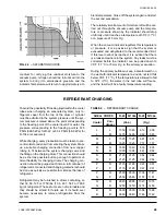
If the system has been pressure tested and found to
be tight prior to evacuation, then the saturation tem-
perature recordings should follow a curve similar to
the typical saturation curve shown as Fig. 22.

The temperature of the water in the test tube will drop
as the pressure decreases, until the boiling point is
reached, at which point the temperature will level off
and remain at this level until all of the water in the shell
is vaporized. When this final vaporization has taken
place the pressure and temperature will continue to
drop until eventually a temperature of 35°F (1.7°C) or
a pressure of 5 mm Hg. is reached.

When this point is reached, practically all of the air
has been evacuated from the system, but there is still
a small amount of moisture left. In order to provide a

Содержание CodePak YK L1 L1 G4

Страница 1: ...ONL R 134a COOLING ONL R 134a COOLING ONL R 134a COOLING ONLY Y Y Y Y WITH MICROCOMPUTER CONTROL CENTER P WITH MICROCOMPUTER CONTROL CENTER P WITH MICROCOMPUTER CONTROL CENTER P WITH MICROCOMPUTER CO...

Страница 2: ...er 160 49 PW5 Wiring Diagram With Solid State Starter 160 49 PW6 STYLES A B YK N2 N1 H1 CX A DESIGN LEVEL A or B POWER SUPPLY for 60 Hz 5 for 50 Hz COMPRESSOR CODE G4 H0 H1 H2 J1 J2 J3 J4 CONDENSER CO...

Страница 3: ...y packaged YORK Solid State Starter op tional In operation a liquid water or brine to be chilled flows through the CodePak cooler where boiling refrigerant absorbs heat from the water The chilled liqu...

Страница 4: ...chilled liquid tempera ture leaving the cooler Prerotation vanes PRV lo cated at the entrance to the compressor impeller com pensate for variation in load See Fig 2 Detail A The position of these vane...

Страница 5: ...r action may be required to correct the interference Additionally any electronic equipment can generate EMI electromagnetic interference which depending upon the installation and magnitude may affect...

Страница 6: ...r alphanumeric display The system setpoints are CHILLED LIQUID TEMPERATURE LCWT INTRODUCTION CURRENT LIMIT PULLDOWN DEMAND LIMIT CLOCK TIME OF DAY DAILY SCHEDULE 7 DAY TIME CLOCK PROGRAM MING HOLIDAY...

Страница 7: ...R VICE 1 Service allows manual PRV control with visual display readout of PRV operation 2 Local allows manual compressor start from the COMPRESSOR switch on the Control Center front 3 Program allows o...

Страница 8: ...c display message EVAP XXX X PSIG COND XXX X PSIG To Display OIL PRESSURE Use OIL PRESSURE display key as described on page 7 to produce the following alphanumeric dis play message OIL PRESSURE XXXX X...

Страница 9: ...tional printers To Display MOTOR CURRENT Press the MOTOR CURRENT display key as described above to display motor current as a per cent of Full Load Amps FLA The message is as follows MOTOR CURRENT XXX...

Страница 10: ...liday see description under HOLIDAY setpoint and the Con trol Center can be programmed usually DAILY SCHED ULE setpoint to automatically start and stop the chiller on those days so designated The oper...

Страница 11: ...435 415 335 362 454 453 440 480 370 400 524 523 550 600 460 502 655 654 SupplyVoltage NONE 0 NONE 0 Range Disabled NOTE The value displayed is the actual LCWT set point For example the value displayed...

Страница 12: ...ribed in the beginning of this section to produce the following message S_ M_ T_ W_ T_ F_ S_ HOLIDAY NOTED BY NOTE On the days that are designated by an the chiller will automatically start and stop p...

Страница 13: ...ed by pressing the ACCESS CODE key again the operator will have ac cess to the PROGRAM key for 10 minutes When 10 minutes have elapsed access to PROGRAM key will be automatically dis abled and the ope...

Страница 14: ...int Electro Mechanical Starter refer to Fig 7 1 Press and release CURRENT LIMIT setpoint key The following program prompt message is displayed CURRENT LIMIT XXX FLA 2 Use Entry keys to enter desired v...

Страница 15: ...INT To Enter CLOCK Setpoint Refer to Fig 9 1 Assure Micro Board Program jumper J57 is in CLKON position 2 Press and release CLOCK setpoint key The fol lowing program prompt message is displayed TODAY...

Страница 16: ...PM key to change AM to PM or vice versa 3 Press and release ADVANCE DAY SCROLL key The following prompt message is displayed MON START XX XX AM STOP XX XX AM 4 Enter the desired start and stop time pe...

Страница 17: ...1 press CANCEL key and then press EN TER key PROGRAM MODE SELECT SETPOINT message is displayed To cancel one of the designated holidays perform Step 1 press ADVANCE DAY SCROLL key until the cursor app...

Страница 18: ...se this key to put the pre rotation vanes under LCWT control as long as the cur rent limit setpoint is not reached which causes the current limit function to override the LCWT control If system is run...

Страница 19: ...gain pressed and re leased Message No 3 is then displayed and updated every 2 seconds until either the DISPLAY DATA key is again pressed and released whereupon message No 1 is displayed or the DISPLAY...

Страница 20: ...10 The mode that has been previously selected will be displayed as follows LOCAL MODE SELECTED or SERVICE MODE SELECTED or REMOTE MODE SELECTED 11 Press ADVANCE DAY key to scroll to desired mode Each...

Страница 21: ...ing to maintain the leaving chilled water temperature set point or The operator has pressed the vanes OPEN key on the keypad SYSTEM RUN VANES CLOSING Displayed when the chiller is running the MicroCom...

Страница 22: ...that the system is not running but will start upon application of a start signal SYSTEM SHUTDOWN PRESS STATUS Displayed when chiller is shut down on a cycling shut down safety shutdown operator must...

Страница 23: ...y pressing the COMPRESSOR switch to the START position REMOTE STOP This message will be displayed when a remote device typically an Energy Management System has com manded the chiller to shut down The...

Страница 24: ...y the motor controller con tacts CM 1 opening and reclosing in one second If Solid State Starter application the shutdown could have been caused by any of the following reasons The ap propriate light...

Страница 25: ...key Or the message will be cleared by initiating a compressor start START SEQUENCE INITIATED Indicates that the Micro Board has received a local or remote start signal and has initiated the chiller st...

Страница 26: ...Auto Zeroing Sequence that occurs 10 seconds after a chiller start is initiated Message is displayed immedi ately after the Auto Zeroing sequence has completed This indicates that one of the transduce...

Страница 27: ...voltage in creases to greater than 19 7VDC MON XX XX AM AUX SAFETY SHUTDOWN The system is shut down because an external device connected to digital input boardTB1 31 Auxiliary Safety Shutdown Input h...

Страница 28: ...MANUAL OIL PUMP key to stop the operation of the oil pump for less than 10 minutes of operation 3 Pre Rotation Vanes To perform this test the starter interlock terminals 3 and 4 must be jump ered to...

Страница 29: ...late oil for a 50 second pre run to establish oil flow and adequate lubrication to all bearings gears and rotating sur faces within the compressor The high and low oil pressure transducers OP and the...

Страница 30: ...vent the Pre rotation Vanes from opening beyond the CURRENT LIMIT setting If the load continues to decrease after the Prerotation Vanes are entirely closed the CodePak will be shut down by the Low Wat...

Страница 31: ...load require ments 2 Be sure the oil pump is operating while unit is run ning 3 Check Oil Pressure display A gradual decrease in bearing oil pressure of 5 to 10 psi 34 5 to 69 kPa with constant sucti...

Страница 32: ...nd leaving chilled liquid tem peratures and evaporator pressure for comparison with job design conditions This can be accomplished by pressing the CHILLED LIQUID TEMPS key and the REFRIGERANT PRESSURE...

Страница 33: ...f auto restart programming jumper is not installed on the Micro Board Low Evaporator Pressure Low Oil Pressure High Condenser Pressure Evaporator Transducer or Probe Error High Discharge Temp High Oil...

Страница 34: ...lled water system chilled water pump and coils Open the drains on the cooler and condenser liquid heads to assure complete drainage If Solid State Starter drain water from starter cooling loop 3 Move...

Страница 35: ...RGE LINE PRE ROTATIONVANE ACTUATOR CONDENSER OIL COOLER OIL RESERVOIR PUMP SUB COOLER OIL PUMP STARTER 27073A 27073A COM PRESSOR ADAPTER MOTOR SUPPORT COVER MOTOR COOLER REFRIGERANT CHARGINGVALVE DEHY...

Страница 36: ...d system consists of the oil pump oil filter oil cooler and all interconnecting oil piping and passages There are main points within the motor compressor which must be supplied with forced lubrication...

Страница 37: ...or independent of the evaporator shell to en sure controlled alignment of the assembly Motor is mounted with final alignment at start up Motor drive shaft is directly connected to the com pressor shaf...

Страница 38: ...38 YORK INTERNATIONAL FIG 18 SCHEMATIC DRAWING YK COMPRESSOR LUBRICATION SYSTEM LD01079...

Страница 39: ...or with lock and key Electrical lugs for incoming power wiring are provided SECTION 5 OPERATIONAL MAINTENANCE OIL RETURN SYSTEM The oil return system continuously maintains the proper oil level in the...

Страница 40: ...nnection at the charging valve until after the air is forced out by pumping a few strokes of the oil pump This fills the lines with oil and prevents air from being pumped into the system 3 Open the oi...

Страница 41: ...of the manual switch Digital input board MON 10 00 AM Multi Unit Autostart Optional Lead Automatic Restart Contact connected to Lag Sequence upon remote the Multi Unit cycling Control command input of...

Страница 42: ...start up MON 10 00 AM Motor Con CM2 or Solid Reset the device CM2 or Solid State troller Ext State Starter that caused the shut Starter has shutdown Reset RT2 down Chiller will chiller start automatic...

Страница 43: ...tor Current Press compressor Check motor starter Malfunction 15 for 10 swc STOP RESET operation Motor current Detected with Control Cen switch and then value greater than 15 ter not calling for FLA mo...

Страница 44: ...normal with normal discharge temperature Temperature of chilled water too low with Insufficient load for Check prerotation vane motor opera with low motor amperes system capacity tion and setting of l...

Страница 45: ...me extremely noisy quantity 8 SYMPTOM OIL PRESSURE GRADUALLY DECREASES Noted by Observation of Daily Log Sheets Oil pressure noted when pressing OIL Oil filter is dirty Change oil filter PRESSURE disp...

Страница 46: ...electronic leak detector can be used to detect any leaks too small to be found by the soap test To test with R 22 proceed as follows 1 With no pressure in the system charge R 22 gas into the system t...

Страница 47: ...mosphere 14 696 PSIA 760 mm Hg absolute pressure at 32 F 29 921 inches Hg absolute at 32 F NOTES PSIA Lbs per sq in gauge pressure Pressure above atmosphere PSIA Lbs per sq in absolute pressure Sum of...

Страница 48: ...c tive method for evacuating and dehydrating a system in the field Although there are several methods of de hydrating a system we are recommending the follow ing as it produces one of the best results...

Страница 49: ...of the drum or cylinder must be admitted to the system pressure until the sys tem pressure is raised above the point corresponding to the freezing point of the cooler liquid For water the pressure cor...

Страница 50: ...ith the method shown under the Refrigerant Charging on page 49 The refrigerant level should be observed and the level recorded after initial charging HANDLING REFRIGERANT FOR DISMANTLING AND REPAIRS I...

Страница 51: ...YORK INTERNATIONAL 51 FORM 160 49 O1 FIG 24 MOTOR STATOR TEMPERATURE AND INSULATION RESISTANCES 110 43 3 100 37 8 90 32 2 80 26 7 70 21 1 60 15 6 50 10 0 40 4 4 TEMPERATURE F C LD01086...

Страница 52: ...pressure over a period of time accompanied by a steady rise in con densing temperature and noisy operation These symp toms may also be due to foul gas buildup Purging will remove the foul gas reveali...

Страница 53: ...nds of all tubes with water NOTE Do not use carbon tetrachloride for this pur pose since its fumes give the same flame discoloration that the refrigerant does 3 With nitrogen or dry air blow out the t...

Страница 54: ...icted oil lines passages or dirty oil fil ters If the unit is shutting down on HOT High Oil Temperature or Low Oil Pressure OP change the oil filter element Examine the oil filter element for the pres...

Страница 55: ...e maintained tight are systems that provide trouble free efficient opera tion COOLER AND CONDENSER The major portion of maintenance on the condenser and cooler will deal with the maintaining the water...

Страница 56: ...y not be changed If the set tings are changed without YORK s approval the warranty will be jeopardized 3 A 5 11 year life battery is part of the RTC Real Time Clock To replace refer to page 25 Proud S...

Отзывы: