


103904-UIM-B-0505
6
Unitary Products Group
NOTE: All wiring must comply with local and national electrical code
requirements. Read and heed all unit caution labels.
NOTE: It is possible to vary the amount of electric heat turned on during
the defrost cycle of a heat pump. Standard wiring will only bring
on 5 - 10 KW of electric heat during defrost, depending on the
size of the heater.
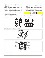
LINE POWER CONNECTIONS
Power may be brought into the unit through the supply air end of the
unit (top when unit is vertical) or the left side panel. Use the hole appro-
priate to the unit’s orientation in each installation to bring conduit from
the disconnect. The power lead conduit should be terminated at the
electrical control box. Refer to Tables 6, 7, 8 for wire requirements. Also
see Figure 11.
BLOWER SPEED COMFORT SELECTION
NOTE:
1.
Both the "COOL" and the "ADJ" tap must be set for the cooling CFM.
2.
Fan only CFM = 63% of high speed cooling.
3.
Low speed cooling used only with two stage outdoor units. (Speed is preset
to 65% of high speed).
4.
Dehumidification speed is 85% of cooling speed.
5.
When operating in both heat pump and electric heat modes, the CFM will be
whichever is greater.
6.
CFM indicator light flashes once for every 100 CFM. (i.e.: 12 Flashes is
1200 CFM)
These variable speed air handlers are designed to deliver constant
CFM regardless of the external static pressure (ESP) in the ductwork.
Therefore, if too many supply registers are closed, a filter becomes
clogged, or there is a restriction in the ductwork, the motor will automat-
ically operate at a higher speed to compensate for the higher ESP. This
may result in a higher operating sound level.
All CFM’s are shown at 0.5” w.c. external static pressure. These units
have variable speed motors that automatically adjust to provide con-
stant CFM from 0.0” to 0.6” w.c. static pressure. From 0.6” to 1.0” static
pressure, CFM is reduced by 2% per 0.1” increase in static. Operation
on duct systems with greater than 1.0” w.c. external static pressure is
not recommended.
To Set Cooling CFM:
Refer to the outdoor unit technical guide for the recommended airflow
with the matching evaporator coil. Refer to the label in the bag attached
to the blower housing or Table 2 for the possible high speed cooling and
heat pump CFM selections.
Find the recommended system airflow in the Table for the installed Air
Handler model.
Select the "COOL" CFM you need from Table 2. Set "COOL" and "ADJ"
Jumpers on the CFM selection board as indicated in Table 2.
To Set Heat Pump CFM:
The heat pump CFM setting is the same as the cooling CFM. No addi-
tional CFM setting is required, however, you must remove the jumper at
the bottom of the connector board labeled "Remove for Heat Pump" for
heat pump operation (See Figure 8).
To Set Electric Heat CFM:
The blower speed required for the Electric Heat is different than cooling.
Refer to the label in the bag attached to the blower housing or Table 2
for the possible CFM selections. Refer to Tables 5 or 6 for the minimum
required CFM for the electric heater installed. Find the desired airflow in
Table 2. Set the "Heat" Jumper on the CFM selection board to tap
shown.
To Set Delay Profile:
Every variable speed air handler has multiple "blower off delay" profiles
to optimize system performance and efficiency. Refer to Table 2 or the
instructions in the bag attached to the blower housing for the type of
system installed. Set the "DELAY" jumper tap position horizontally on
the CFM selection board for the appropriate setting.
Fan Only CFM:
When the connection is made from "R" to "G", the fan only mode is acti-
vated. In this mode, the blower will deliver 63% of the cooling system
CFM. This connection is factory set from the manufacturer and cannot
be field adjusted.
To Install Humidistat Accessory:
If the system is used with a humidistat accessory, connect the field
wires to screw terminals "R" and "Hum" on the CFM selection board
(See Figures 12, 13, 14, 15, 16, 17, 18, 19, and 20).
IMPORTANT: Remove the jumper at the bottom of the connector board
marked "Remove for Humidistat" for humidistat operation.
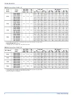
TABLE 2: CFM / Comfort Tap Selection
HIGH SPEED COOLING AND HEAT PUMP CFM
MODEL JUMPER
SETTING
N1VSB12 N1VSD12 N1VSC16 N1VSD20
"COOL
TAP"
"ADJ
TAP"
1250 1400
1650 2100 "A" "B"
1230 1230
1570 1980 "B" "B"
1150 1220
1500 1860 "A" "A"
1070 1070
1425 1750 "B" "A"
1035 1100
1350 1675 "A" "C"
1000 1000
1305 1605 "C" "B"
965 965
1285
1575 "B" "C"
820 820
1220
1510 "D" "B"
870 870
1185
1420 "C" "A"
715 715
1110
1335 "D" "A"
785 785
1065
1280 "C" "C"
645 645
1000
1200 "D" "C"
COMFORT SETTING
"DELAY" TAP
UNIT TYPE
Jumper at "A"
Normal Profile
Jumper at "B"
Humid Profile
Jumper at "C"
Dry Profile
Jumper at "D"
Temperate Profile
ELECTRIC HEAT CFM
MODEL
TAP
SELECTIONS
N1VSB12
N1VSD12
N1VSC16
N1VSD20
"HEAT"
1150 1220
1500
1860 "A"
1070 1070
1425
1750 "B"
870 870
1185
1420 "C"
715 715
1110
1335 "D"
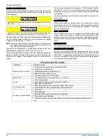
FIGURE 8: CFM Selection Board Detail
DO NOT change the "ADJ" tap position on the CFM selection board
as this will change your cooling CFM previously selected.
CFM SELECTION BOARD
TAP SELECTION
D
C
B
A
D
C
B
A
COOL
HEAT
ADJ
DELAY
REMOVE FOR
HEAT PUMP
HUMIDISTAT


