background image

4-32

IM 04P03B01-01E

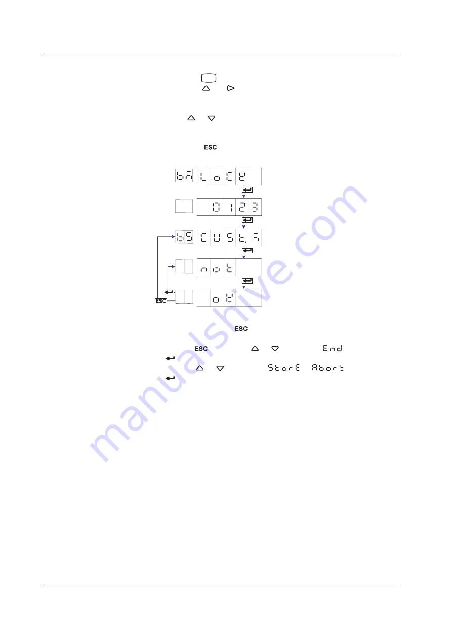
Disabling the Customized Menu

1.

Hold down the 

MENU

 key for 3 seconds to enter Setting mode.

2.

Hold down the 

 and 

 keys simultaneously for 3 seconds to display the

Basic Setting mode screen.

3.

Carry out the procedure shown in the figure below.
Press the 

 or 

 key to select the value.

For the procedure on how to enter values or characters, see page 19 in the

Operation Guide

.

If you press the 

 key, the operation is cancelled, and the display returns to a

higher level menu.

Enter the password.

Enter Basic Setting mode.

Select “LOCK.”

(LOCK)

(****)

Select NOT.

Select “CUST.M.”

(CUST.M)

(NOT)

The settings are activated.

(OK)

4.

If you are done, press the 

 key.

5.

To return to the Operation mode,
1. Press the 

 key, use the 

 or 

 key to select 

, and press the

 key.

2. Press the 

 or 

 key to select 

 or 

, and press the

 key.

4.21  Enabling/Disabling the Customized Menu

Содержание SR10000 series

Страница 1: ...User s Manual Yokogawa Electric Corporation Models SR10001 SR10002 SR10003 SR10004 SR10006 SR10000 Recorder IM 04P03B01 01E 2nd Edition ...

Страница 2: ...t of continuing improvements to the instrument s performance and functions Every effort has been made in the preparation of this manual to ensure the accuracy of its contents However should you have any questions or find any errors please contact your nearest YOKOGAWA dealer as listed on the back cover of this manual Copying or reproducing all or any part of the contents of this manual without the...

Страница 3: ...ing functions such as setting the recorder to detect sensor burnouts and changing the contents that are printed on the chart paper 5 Troubleshooting Describes error message and troubleshooting measures of the SR10000 Recorder 6 Maintenance Describes periodic inspection calibration and pen adjustment printer carriage adjustment 7 Specifications Gives the specifications of the SR10000 Recorder Appen...

Страница 4: ...precautions that can be taken to prevent such occurrences CAUTION Calls attentions to actions or conditions that could cause light injury to the user or damage to the instrument or user s data and precautions that can be taken to prevent such occurrences Note Calls attention to information that is important for proper operation of the instrument Subheadings On pages that describe the operating pro...

Страница 5: ...ring 3 8 3 9 Setting the Secondary Chart Speed Remote Control Function R1 3 9 3 10 Applying a Bias on the Measuring Input Signal 3 10 3 11 Performing Calibration Correction CC1 Option 3 11 3 12 Setting Up Start Printout and End printout BT1 Option 3 13 3 13 Regarding the Message Format BT1 Option 3 18 3 14 Setting the Date Time for Switching between Standard Time and DST 3 20 Chapter 4 Setup Opera...

Страница 6: ...ting the Calibration Correction Function CC1 Option 4 34 4 23 Enabling Start Printout End printout and Message Format BT1 Option 4 35 4 24 Changing the Temperature Unit 4 37 Chapter 5 Troubleshooting 5 1 A List of Error Messages 5 1 5 2 Troubleshooting Flow Charts 5 4 Chapter 6 Maintenance 6 1 Periodic Inspection 6 1 6 2 Cleaning the Recorder 6 2 6 3 Calibrating the Recorder 6 3 6 4 Adjusting the ...

Страница 7: ...sured values Also the low cut function input less than 0 is fixed to 0 scale left value can be used Current Input A shunt resistor is attached to the input terminal The current signal is converted to a voltage signal and measured The measurable range is the range equivalent to the DC voltage range indicated above after converting the current to the voltage signal Note Three types of shunt resistor...

Страница 8: ...utation cannot be designated Scaling The input values are scaled to values in the appropriate unit to be used as measured values 0 V 100 0 C 10 V 300 0 C Measured value Input value Square Root Computation When the input type is DC voltage the square root of the input value is calculated the result is scaled to a value in the appropriate unit and used as the measured value of the channel Also the l...

Страница 9: ...d value A Correction value B A Scale value Calibration point Correction using absolute values Measured value A Correction value B A1 A2 A3 A4 A5 Related Topics Setting the calibration correction function Sections 4 15 4 22 and 3 11 Burnout Detection of Thermocouples This function makes the recording go off the scale to the right or left when the thermocouple burns out while measuring temperature w...

Страница 10: ...nel However it does not operate on channels set to ON OFF input Filter Pen Model The filter is a low pass filter The time constant can be set to 2 s 5 s or 10 s 63 2 of the output value 2 5 10 s time constant the time it takes to reach 63 2 of the output value Output response curve when using the filter Input signal Filter result output for a step input Moving Average Dot Model The average value o...

Страница 11: ...ation Time of the A D Converter Pen model Select 16 7 ms 60 Hz 20 ms 50 Hz or Auto Dot model Select 16 7 ms 60 Hz 20 ms 50 Hz 100 ms or Auto If Auto is selected the recorder detects the power supply frequency and automatically selects 16 7 ms or 20 ms If Auto is specified when using the 24 VDC power supply on a recorder with the 24 VDC AC power supply P1 option the integration time is fixed to 20 ...

Страница 12: ...High limit alarm Low limit alarm Measured value Alarm release Alarm value Alarm occurrence Difference High Limit Alarm h An alarm occurs when the difference in the input values of two channels is greater than or equal to the specified value Difference Low Limit Alarm l An alarm occurs when the difference in the input values of two channels is less than or equal to the specified value Can be specif...

Страница 13: ...e energizes when an error is detected de energized operation Note If diagnosis output is enabled I01 becomes a relay dedicated to diagnosis output Related Topics Setting the diagnosis output Section 4 1 Energized De energized Operation of Alarm Output Relays You can select whether the alarm output relay is energized or de energized when an alarm occurs If de energized is selected the status of the...

Страница 14: ...the dots do not overlap The other method records at the fastest dot printing interval at all times The recording colors in order from channel 1 are purple red green blue brown and black The recording color of each channel can be changed among these six colors For each channel trend recording can be enabled or disabled Related Topics Setting the trend recording interval Section 3 1 Changing the rec...

Страница 15: ... the time axis On 2 pen 3 pen and 4 pen recorders there are offsets along the time axis phase difference between the pens This offset is corrected when pen offset compensation is used Same time Below is an explanation for the 2 pen model The recording of these two pens are offset by an amount of phase P If pen offset compensation is enabled the measured values of pen 1 are stored in the memory and...

Страница 16: ...icks are marks that indicate the positions of the date time on the chart paper Time tick cancel mark An exclamation point is printed when the periodic printout time tick was not printed at the correct position Channel number or tag printout Channel numbers or tags can be printed Related Topics Switching between channel number printout and tag printout Section 4 7 Setting the periodic printout inte...

Страница 17: ...rding The channel No or tag is printed every approximately 25 mm on the chart paper The channel printout can be enabled or disabled By default the channel printout is enabled Related Topics Switching between channel number printout and tag printout Section 4 7 Setting the periodic printout interval reference time and periodic printout ON OFF Section 4 8 Turning printout ON OFF channel printout ala...

Страница 18: ...n model asterisks are printed Channel data Prints the channel numbers or tags measured values instantaneous values and units Alarm status Prints the alarm that is occurring Prints the letter d on channels set to delta computation If multiple alarms are occurring the alarm with the highest precedence is printed Alarm printout precedence Higher H L h and l lower Scale Prints the leftmost and rightmo...

Страница 19: ...an be selected Manual Printout Measured values and alarm status can be printed manually using the keys When manual printout is executed trend recording stops and restarts when manual printout is complete For the operation procedure see the Operation Guide Message Printout Printout cannot be performed at the following chart speeds Pen model 1800 mm h or higher Dot model 120 mm h or higher Preset me...

Страница 20: ...3 06 Day Month Year 31 03 2006 31 03 06 Month Day Year Mar 31 2006 03 31 06 1 These do not apply for the date printout format for message printouts that include measured values BT1 option Specify that in the message format Printout Format of the Time The printout format of the time can be selected from the list below Selectable Type Printout Format Notes Settings Example Hour Minute 10 00 Default ...

Страница 21: ...arts when the printout is complete List printout contains Setting Mode settings such as the input range and alarm for each channel Setup List contains Basic Setting Mode settings such as the alarm output relay operation and printout method Printout Example of List on the Pen Model The printout examples may appear differently from the actual printout as a result of functional improvements made on t...

Страница 22: ...ions see section 1 6 Function Setup Guide Printout Example of List on the Dot Model The printout examples may appear differently from the actual printout as a result of functional improvements made on the recorder after this manual was written 1 3 Recording ...

Страница 23: ...result of functional improvements made on the recorder after this manual was written Start Printout and End printout You can set Start printout and Start printout 2 for the printout when recording starts Also you can set End printout and End printout 2 for the printout when recording stops Printout Operation Description Notes Comment Prints 32 characters x 5 lines or less Batch name Batch number P...

Страница 24: ...itching signal Start Stop Concluded successfully Concluded unsuccessfully Start printout End printout Start Stop Start printout End printout 2 Message Printout Including Measured Values Following the specified message format the date time message strings of the standard function 5 strings of up to 16 characters and measured instantaneous values are printed out together Up to 5 messages of 35 chara...

Страница 25: ...The chart paper is fed at the secondary chart speed while a level signal is applied to the terminal The secondary chart speed is set in advance Internal Clock Adjustment Remote input signal Trigger The internal clock of the recorder is adjusted to the nearest hour depending on the time when the remote signal is applied Time When Signal Is Input Adjustment 00 min 00 s to 01 min 59 s Truncates the m...

Страница 26: ...ng edge of the remote signal edge the ON signal lasting at least 250 ms trigger or the ON OFF signal level Rising Falling edge Trigger Level Rising Falling 250 ms or more Operates at the secondary chart speed 250 ms or more For contact inputs the remote signal rises when the contact switches from open to closed and falls when the contact switches from closed to open For open collector signals the ...

Страница 27: ...s that you use Display only the items that you use on the FUNC key menu Display only the items that you use on the Setting mode menu Lock Basic Setting mode use a password to enter the mode The pen position adjustment pen model and dot printing position adjustment dot model can be set so that they can be used without the password Operation mode Setting mode Displays only the FUNC key menu items to...

Страница 28: ... switching from the standard time to DST and the date time when switching back from DST to standard time When switching from standard time to DST the clock is set ahead by 1 hour When switching back from DST to standard time the clock is set back by 1 hour Related Topics Using the DST Section 3 14 Temperature Unit The temperature unit can be set to Celsius or Fahrenheit The setting applies to all ...

Страница 29: ... not appear in the RANGE setting Scaling Range span and scale 2 1 Use RANGE in Setting mode Unit 2 3 Use UNIT in setting mode to set the unit after scaling Square Root Computation Range span and scale 2 1 Use RANGE in Setting mode Unit 2 3 Use UNIT in setting mode to set the unit after scaling Low cut 4 15 Use PERS SQRT low cut in Basic Setting mode and select Use or Not If Use is selected set the...

Страница 30: ...IAG in Basic Setting mode to set the function 4 1 Change the alarm output relay operation If ALARM RELAY in Basic Setting mode set to DE_EN alarm output relay is 4 1 energized during normal operation and de energized when an alarm occurs Recording functions Item Description Reference Section Recording interval dot model Use AUX TREND in Setting mode to set the recording interval to AUTO or FIX 3 1...

Страница 31: ...Use T_PRN ALARM in Basic Setting mode to set the time printout format when printing alarm occurrence release Message printout Set the message string 3 8 Use AUX MSG to set the message string to be printed Time printout format 4 16 Use T_PRN MSG in Basic Setting mode to set the time printout format Execute the message printout Operation Guide Use FUNC key MSG in Operation mode to execute the messag...

Страница 32: ...nctions 4 14 Other functions Item Description Reference Section Key lock Target keys and password 4 9 Use LOCK in Basic Setting mode to set the keys to be key locked and the password Enable the key lock Operation Guide Use FUNC key LOCK in Operation mode to turn key lock ON OFF Activating Releasing the Key Lock Customize menu FUNC key target menu selection 4 19 Use S MENU FUNC in Basic Setting mod...

Страница 33: ...r the procedure on how to enter values or characters see page 19 in the Operation Guide To change the polarity press the or key when the leftmost digit of the value is blinking If you press the key the operation is cancelled and the display returns to a higher level menu Select the input type Select the channel number Select the range Set the left span value Set the right span value The settings a...

Страница 34: ...72 0 F J 200 0 to 1100 0 C 328 0 to 2012 0 F T 200 0 to 400 0 C 328 0 to 752 0 F N 0 0 to 1300 0 C 32 to 2372 F W 0 0 to 2315 0 C 32 to 4199 F L 200 0 to 900 0 C 328 0 to 1652 0 F U 200 0 to 400 0 C 328 0 to 752 0 F WRe 0 0 to 2400 0 C 32 to 4352 F RTD Range Type Selectable Span Range C Selectable Span Range F PT Pt100 200 0 to 600 0 C 328 0 to 1112 0 F JPT JPt100 200 0 to 550 0 C 328 0 to 1022 0 ...

Страница 35: ...e Right and Decimal Place Selectable range mantissa 19999 to 30000 Example The value in the range of 100 00 to 350 00 cannot be specified The mantissa of scale right is 35000 which exceeds the upper limit to 30000 Set in the range of 100 0 to 350 0 Decimal place XXXXX XXXX X XXX XX XX XXX X XXXX To set the decimal place for the left scale setup item press the key to make blink then press the or ke...

Страница 36: ... as the selectable span range of the DC voltage Thermocouple and RTD range Scale Left Scale Right and Decimal Place Selectable range mantissa 19999 to 30000 Example The value in the range of 100 00 to 350 00 cannot be specified The mantissa of scale right is 35000 which exceeds the upper limit to 30000 Set in the range of 100 0 to 350 0 Decimal place XXXXX XXXX X XXX XX XX XXX X XXXX To set the de...

Страница 37: ...e value Input Type Range Type Selectable Span Range C Selectable Span Range F DC voltage 20 mV 20 00 to 20 00 mV 60 mV 60 00 to 60 00 mV 200 mV 200 0 to 200 0 mV 2 V 2 000 to 2 000 V 6 V 6 000 to 6 000 V 20 V 20 00 to 20 00 V 50 V 50 00 to 50 00 V Thermocouple R 1760 0 to 1760 0 C 3168 to 3168 F S 1760 0 to 1760 0 C 3168 to 3168 F B 1820 0 to 1820 0 C 3276 to 3276 F K 1570 0 to 1570 0 C 2826 to 28...

Страница 38: ...H1 DI CONT OK Channel number Span left Span right Description Selectable Range of Input Range Span Left and Span Right The input range span left and span right can be set in the range shown below Span left and span right cannot be set to the same value Range Type Selectable Span Values Level 0 Less than 2 4 V 1 2 4 V or higher within 6 V Contact 0 Open 1 Closed 2 1 Setting the Input Range ...

Страница 39: ...int Description Input Type on Which Square Root Computation Can Be Performed Square root computation can be performed when set to DC voltage input Span Left and Span Right Same as the selectable span range of the DC voltage range Make sure that span left is less than span right Scale Left Scale Right and Decimal Place Selectable range mantissa 19999 to 30000 Example The value in the range of 100 0...

Страница 40: ...t point is set to 0 of the recording span scale left value Related Topics Setting the unit Section 2 3 Enabling the low cut function Section 4 15 Skip Unused Channels Select SKIP Select the channel number The settings are activated Select RANGE RANGE CH1 SKIP OK Channel number Note Do not use channels set to skip as a reference channel of delta computations 2 1 Setting the Input Range ...

Страница 41: ...ng If you press the key the operation is cancelled and the display returns to a higher level menu ALARM CH1 L4 ON H ON I01 OK Select the level number between 1 and 4 Select the channel number Select ON to set the alarm Displays the following when the alarm is ON Select the alarm type Set the value used to turn ON the alarm When the alarm output is ON Specify the alarm output relay number The setti...

Страница 42: ...es can be specified For DC voltage thermocouple or RTD Values within the measurable range in the input range example 2 000 to 2 000 V for the 2 V input range For ON OFF input DI 0 or 1 For linear scaling 1 5V scaling and square root A value within 5 to 105 of the scaling span and within the range of 19999 to 30000 excluding the decimal point Difference High Limit Alarm Difference Low Limit Alarm V...

Страница 43: ...ter the ASCII code of the 6th character The settings are activated Select UNIT UNIT CH1 OK 1st char 1st character ASCII code 3rd character ASCII code 2nd character ASCII code 6th character ASCII code 2nd char SP Space Example To register A enter 41 0 1 2 3 4 5 6 7 8 A B C D E F G H P Q R S T U V W X a b c d e f g h p q r s t u v w x SP 9 0 1 2 3 4 5 6 7 8 9 A B C D E F I J K L M N O Y Z i j k l m ...

Страница 44: ...OK 3 If you are done press the key 4 Hold down the MENU key for 3 seconds to return to Operation mode Explanation Chart Speed Pen model Select from the 40 settings shown below Dot model Select from the 28 settings in the thick frame shown below 10 15 20 25 30 40 50 60 75 80 90 100 120 150 160 180 200 240 300 360 375 450 600 720 750 900 1200 1500 1800 2400 3000 3600 4500 4800 5400 6000 7200 9000 10...

Страница 45: ...ts the hour minute and second Set the year month and day The settings are activated Select CLOCK CLOCK OK Year Month Hour Minute Second Day 3 If you are done press the key 4 Hold down the MENU key for 3 seconds to return to Operation mode Explanation Date Time Set the lower two digits of the year Values in the range 80 and 99 correspond to 1980 to 1999 Note When setting the date time the year mont...

Страница 46: ...he AUX AUX TREND AUTO OK 3 If you are done press the key 4 Hold down the MENU key for 3 seconds to return to Operation mode Explanation Trend Recording Interval AUTO The trend recording interval is set according to the chart speed so that the dots do not overlap FIX The trend recording interval is fixed to 10 s 6 dots When set to AUTO When set to FIX Dot Recording Intervals When AUTO Is Selected C...

Страница 47: ...ncelled and the display returns to a higher level menu Select the channel number Select FILTR Select the filter time constant The settings are activated Select the AUX AUX FILTR CH1 OFF OK Channel number 3 Press the key to set other channels If you are done press the key 4 Hold down the MENU key for 3 seconds to return to Operation mode Explanation Filter Time Constant The time constant is selecta...

Страница 48: ...ration is cancelled and the display returns to a higher level menu Select the channel number Select M_AVE Select the number of samples of the moving average The settings are activated Select the AUX AUX M_AVE CH1 OFF OK Channel number 3 Press the key to set other channels If you are done press the key 4 Hold down the MENU key for 3 seconds to return to Operation mode Explanation Number of Samples ...

Страница 49: ...et the leftmost position of the recording zone Set the rightmost position of the recording zone The settings are activated Select the AUX AUX ZONE CH1 OK Channel number Leftmost position Rightmost position 3 Press the key to set other channels If you are done press the key 4 Hold down the MENU key for 3 seconds to return to Operation mode Explanation Recording Zone The recording zone can be set in...

Страница 50: ...the channel number Select the PART Select ON to set the partial expanded recording function When partial expanded recording is ON Set the boundary position A value when the record span is assumed to be 100 Set the boundary value within the recording span Select the AUX AUX PART CH1 ON The settings are activated OK Channel number Boundary position Boundary value 3 Press the key to set other channel...

Страница 51: ...l menu Select the channel number Select PRINT Dot model only Turn trend recording ON OFF Select whether to print the measured values in periodic printout Select the AUX AUX PRINT CH1 ON ON The settings are activated OK Trend recording Periodic printout 3 Press the key to set other channels If you are done press the key 4 Hold down the MENU key for 3 seconds to return to Operation mode Explanation ...

Страница 52: ...st char 2nd char 1st character ASCII code 3rd character ASCII code 2nd character ASCII code 7th character ASCII code SP Space Example To register A enter 41 0 1 2 3 4 5 6 7 8 A B C D E F G H P Q R S T U V W X a b c d e f g h p q r s t u v w x SP 9 0 1 2 3 4 5 6 7 8 9 A B C D E F I J K L M N O Y Z i j k l m n o y z µ Ω 2 3 Lower Upper 20 30 40 50 60 70 0 1 2 3 4 5 6 7 8 A B C D E F G H P Q R S T U ...

Страница 53: ...activated 1st character ASCII code 3rd character ASCII code 2nd character ASCII code 16th character ASCII code SP Space Example To register A enter 41 0 1 2 3 4 5 6 7 8 A B C D E F G H P Q R S T U V W X a b c d e f g h p q r s t u v w x SP 9 0 1 2 3 4 5 6 7 8 9 A B C D E F I J K L M N O Y Z i j k l m n o y z µ Ω 2 3 Lower Upper 20 30 40 50 60 70 0 1 2 3 4 5 6 7 8 A B C D E F G H P Q R S T U V W X ...

Страница 54: ...s to enter Setting mode 2 Carry out the procedure shown in the figure below Press the or key to select the value If you press the key the operation is cancelled and the display returns to a higher level menu Select the secondary chart speed Select SPD_2 The settings are activated Select the AUX AUX SPD_2 OK 3 If you are done press the key 4 Hold down the MENU key for 3 seconds to return to Operati...

Страница 55: ... a higher level menu BIAS CH1 ON OK Select ON to set the bias Select the channel number The settings are activated When bias is ON Enter the bias value Select BIAS Channel number 3 Press the key to set other channels If you are done press the key 4 Hold down the MENU key for 3 seconds to return to Operation mode Explanation Bias The range of bias that can be specified is approximately 10 of the me...

Страница 56: ...key the operation is cancelled and the display returns to a higher level menu CALIB CH1 ON STORE ON Select ON to set the calibration correction Select the channel number Enter the correction value of the 1st point Displays the following when the calibration correction is ON Enter the measured value of the 1st point Select CALIB Enter the measured value of the 2nd point Enter the correction value o...

Страница 57: ...sing revise values A1 A2 A3 A16 A1 B1 A2 B2 A3 B3 A16 B16 A and B are within the measurable range or scaling range of the range type Within the scaling range 5 to 105 of the scale value or 19999 to 30000 the decimal place is the same as the setting for the scale value Setting range of measured and correction values when using absolute values A1 A2 A3 A16 B1 B2 B3 B16 A and B are within the measura...

Страница 58: ...ch Number Select B NUM batch number Select BATCH BATCH B NUM Enter ASCII code for the 1st character Enter ASCII code for the 2nd character Enter ASCII code for the 3rd character OK 1st char 2nd char Enter ASCII code for the 26th character The settings are activated 1st character ASCII code 3rd character ASCII code 2nd character ASCII code 26th character ASCII code SP Space Example To register A en...

Страница 59: ...atch details Select BATCH BATCH DETAI 3rd character ASCII code Enter the 2nd character 2nd char 2nd character ASCII code 1st char batch details 1st character ASCII code SP Space Example To register A enter 41 0 1 2 3 4 5 6 7 8 A B C D E F G H P Q R S T U V W X a b c d e f g h p q r s t u v w x SP 9 0 1 2 3 4 5 6 7 8 9 A B C D E F I J K L M N O Y Z i j k l m n o y z µ Ω 2 3 Lower Upper 20 30 40 50 ...

Страница 60: ... BATCH Select DETAI Batch details Start 2 and End 2 can be selected when dual comment is set to USE Select a mode Select PRINT printout BATCH DETAI START PRINT B NAME ON C_SPD ON CLOCK ON The settings are activated OK Select whether to printout date time Select ON or OFF Select whether to printout chart speed Select ON or OFF Select whether to printout Batch name Batch No and Lot No Select ON or O...

Страница 61: ...ly when pen offset compensating data ejection is ON Select the chart speed when ejecting the pen offset compensating data Only when the mode is End or End 2 and the lot number is 4 or 6 digits Select to update the lot number when recording stops Only when the mode is End or End 2 and pen offset compensating is ON on pen models Select to eject the pen offset compensating data when recording stops b...

Страница 62: ... model You can eject the portion that is not recorded when recording stops ON Eject OFF Do not eject Chart Speed When Ejecting Pen Offset Compensating Data pen model Select the chart speed when ejecting the portion that was not recorded Current chart speed Feeds at the specified chart speed 450 Fixed to feed at 450 mm h Note The following operations are performed when using the header printout fun...

Страница 63: ...sage 1 printout result 06 30 10 10 Process 1 134 8 C Message format 1 M D H M L09 01L02 Measured value on CH1 no units Space number of characters 1 Space 1 9th characters of the message string Date time Date Time Format and Number of Characters Used H M Hour Minute 5 characters H M S Hour Minute Second 8 characters M D H M Month Day Hour Minute 11 characters M D H M S Month Day Hour Minute Second ...

Страница 64: ... The format for message strings is L01 1 character L02 2 characters L16 16 characters In the example on the previous page L09 indicates Process 1 and L02 indicates C Related Topics Enabling the message format Section 4 23 Setting message strings Section 3 8 3 13 Regarding the Message Format BT1 Option ...

Страница 65: ...ng mode 2 Carry out the procedure shown in the figure below Press the or key to select the value If you press the key the operation is cancelled and the display returns to a higher level menu Select whether to use the DST function Select DST Displays the following when the DST function is set to USE Select the start month Select the AUX AUX DST USE Select the start week Select the start day LAST S...

Страница 66: ...h day of the week of the month End Month End Day and End Time Set the date time for switching from DST to standard time Specify the day as the nth day of the week of the month Start Month and End Month 01 to 12 January to December Start Week and End Week 1 1st week 2 2nd week 3 3rd week 4 4th week Last week Start Day and End Day Sunday Monday Tuesday Wednesday Thursday Friday Saturday Start Time a...

Страница 67: ...n in the figure below Press the or key to select the value If you press the key the operation is cancelled and the display returns to a higher level menu The settings are activated Select the ALARM RANGE DIAG ON RELAY ENERG HYS OFF OK Diagnosis output Select ON to set relay I01 to diagnosis output This setting is valid only on models with the A1 A2 or A3 option Output relay energize de energize Se...

Страница 68: ...put relay is energized or de energized when an alarm occurs Energize Energizes the relay when an alarm occurs The relay is de energized during normal operation De energize De energizes the relay when an alarm occurs The relay is energized during normal operation Hysteresis Sets the alarm hysteresis of the measurement channels The hysteresis width can be set in the range of 0 0 OFF to 1 0 of the re...

Страница 69: ...o a higher level menu The settings are activated Select the integration time of the A D converter Select INTG INTG AUTO OK 4 If you are done press the key 5 To return to the Operation mode 1 Press the key use the or key to select and press the key 2 Press the or key to select or and press the key Explanation Integration Time Selects the integration time of the A D converter Selectable Settings Int...

Страница 70: ...ation is cancelled and the display returns to a higher level menu Select the recording operation that is carried out when a burnout is detected Select the channel number The settings are activated Select B_OUT B_OUT CH1 OFF OK Channel number 4 Press the key to set other channels If you are done press the key 5 To return to the Operation mode 1 Press the key use the or key to select and press the k...

Страница 71: ...king If you press the key the operation is cancelled and the display returns to a higher level menu Select the RJC mode of the thermocouple input Select the channel number When external EXT is selected Set the compensation voltage when using the external RJC function Selects RJC RJC CH1 INT Channel number The settings are activated OK 4 Press the key to set other channels If you are done press the...

Страница 72: ...lue If you press the key the operation is cancelled and the display returns to a higher level menu Select the recording color Select the channel number The settings are activated Select COLOR COLOR CH1 PRPLE OK Channel number 4 Press the key to set other channels If you are done press the key 5 To return to the Operation mode 1 Press the key use the or key to select and press the key 2 Press the o...

Страница 73: ...ncelled and the display returns to a higher level menu The settings are activated Select ON to record by compensating for the pen offset along the time axis Select POC POC OFF OK 4 If you are done press the key 5 To return to the Operation mode 1 Press the key use the or key to select and press the key 2 Press the or key to select or and press the key Explanation When pen offset compensation is tu...

Страница 74: ...cedure shown in the figure below Press the or key to select the value If you press the key the operation is cancelled and the display returns to a higher level menu Select the channel tag printout Select whether to use the channel numbers CH or tags TAG for the printout Select PRINT PRINT CH TAG CH CHPRN ON ALARM ON1 RCD OFF SPEED ON Channel printout Dot model only Select whether to print the chan...

Страница 75: ...one press the key 5 To return to the Operation mode 1 Press the key use the or key to select and press the key 2 Press the or key to select or and press the key Explanation Channel Tag Printout Channel Prints the channel number Tag Prints the tag Alarm Printout ON1 Prints the alarm information when an alarm occurs or releases ON2 Prints the alarm information only when an alarm occurs OFF Does not ...

Страница 76: ...et the reference time for the printout Select the periodic printout interval mode Select PER PER AUTO 00 00 When the interval mode is manual Select the periodic printout interval 1H Select whether to enable INST or disable OFF the periodic printout INST The settings are activated OK 4 If you are done press the key 5 To return to the Operation mode 1 Press the key use the or key to select and press...

Страница 77: ... 8 12 and 24 hours to However printout might not take place at the specified interval depending on the chart speed and items printed for details see appendix 1 Turning ON OFF the Periodic Printout ON instantaneous value Prints the measured value at that point OFF Disables periodic printout 4 8 Turning Periodic Printout ON and OFF and Setting the Interval ...

Страница 78: ...to select the value For the procedure on how to enter values or characters see page 19 in the Operation Guide If you press the key the operation is cancelled and the display returns to a higher level menu Select LOCK LOCK USE RCd FREE FEED FREE MENU RCD key Select whether to lock the key LOCK or FREE FEED key Select whether to lock the key LOCK or FREE FREE MENU key Select whether to lock the key ...

Страница 79: ...REE B CLR FREE Printout buffer clear Select whether to lock the key LOCK or FREE PEN FREE Pen exchange Pen model only Select whether to lock the key LOCK or FREE RIBON The settings are activated FREE OK Ribbon exchange Dot model only Select whether to lock the key LOCK or FREE From the previous page 4 If you are done press the key 5 To return to the Operation mode 1 Press the key use the or key to...

Страница 80: ...C key manual printout operation LIST FUNC key list printout operation SLIST FUNC key setup list printout operation MSG FUNC key message printout operation B_CLR FUNC key clear operation of the printout buffer memory PEN FUNC key the operation of moving the pen to an easily accessible position of replacement pen model RIBON FUNC key the operation carried out when replacing the ribbon cassette with ...

Страница 81: ...cedure shown in the figure below Press the or key to select the value If you press the key the operation is cancelled and the display returns to a higher level menu The settings are activated Select whether to use moving average function Select M_AVE M_AVE NOT OK 4 If you are done press the key 5 To return to the Operation mode 1 Press the key use the or key to select and press the key 2 Press the...

Страница 82: ...re below Press the or key to select the value If you press the key the operation is cancelled and the display returns to a higher level menu The settings are activated Select whether to use the filter function Select FILTR FILTR NOT OK 4 If you are done press the key 5 To return to the Operation mode 1 Press the key use the or key to select and press the key 2 Press the or key to select or and pre...

Страница 83: ... or key to select the value If you press the key the operation is cancelled and the display returns to a higher level menu The settings are activated Select whether to use the partial expanded recording function Select the PART PART NOT OK 4 If you are done press the key 5 To return to the Operation mode 1 Press the key use the or key to select and press the key 2 Press the or key to select or and...

Страница 84: ...urn to the Operation mode 1 Press the key use the or key to select and press the key 2 Press the or key to select or and press the key Explanation Font English Uses the alphabet numbers and symbols for printout Japanese Uses the alphabet Katakana numbers and symbols for printout German Uses the German alphabet numbers and symbols for printout French Uses the French alphabet numbers and symbols for...

Страница 85: ...ut the procedure shown in the figure below Press the or key to select the value If you press the key the operation is cancelled and the display returns to a higher level menu The settings are activated Select the date format Select DATE DATE YMD OK 4 If you are done press the key 5 To return to the Operation mode 1 Press the key use the or key to select and press the key 2 Press the or key to sele...

Страница 86: ... If you press the key the operation is cancelled and the display returns to a higher level menu Select PERS PERS BIAS NOT SQRT USE 1 5V NOT CALIB NOT The settings are activated OK Bias function Select enable USE or disable NOT Low cut function of the channel on which square root computation is assigned Select enable USE or disable NOT Low cut function of the channel on which 1 5V signal is assigne...

Страница 87: ... setting of the low cut function when a channel is set to 1 5V in Setting mode Disable The 1 5V item does not appear in Setting mode Calibration Correction CC1 Option Enable Enables the setting of the calibration correction function in Basic Setting and Setting modes Disable The CALIB item does not appear in Basic Setting or Setting mode Note The bias and calibration correction functions CC1 optio...

Страница 88: ... the procedure shown in the figure below Press the or key to select the value If you press the key the operation is cancelled and the display returns to a higher level menu Select T_PRN T_PRN ALARM HM MSG HM RCD HM SPEED HM The settings are activated OK Alarm printout Select the time printout format Message printout Select the time printout format Recording start printout Select the time printout ...

Страница 89: ...Hour Minute H M S Hour Minute Second M D H M Month Day Hour Minute M D H M S Month Day Hour Minute Second Y M D H M S Year Month Day Hour Minute Second Message Printout H M Hour Minute H M S Hour Minute Second M D H M Month Day Hour Minute M D H M S Month Day Hour Minute Second Y M D H M S Year Month Day Hour Minute Second NONE Does not print the date time Note The printout format of the year mont...

Страница 90: ...he Basic Setting mode screen 3 Carry out the procedure shown in the figure below Press the or key to select the value If you press the key the operation is cancelled and the display returns to a higher level menu Select YES and press to execute the initialization and return to Operation mode Select the range to be initialized Select INIT INIT SETUP NO Explanation Initialization Set Initializes the...

Страница 91: ...seconds to display the Basic Setting mode screen 3 Carry out the procedure shown in the figure below Press the or key to select the value If you press the key the operation is cancelled and the display returns to a higher level menu Select the function to be assigned Select the remote control terminal number The settings are activated Select REM REM REM1 RCD OK Remote control terminal number 4 Pre...

Страница 92: ... message 4 MSG5 Prints message 5 PR RCD Starts stops recording BT1 option DUAL Start printout and Start printout 2 End printout and End printout 2 switches according to the status of the PR RCD signal during the rising or falling of the RCD or PR RCD signal BT1 option NONE No function is assigned Note When you select PR RCD and start recording remotely you cannot stop recording using key operation...

Страница 93: ...lay the Basic Setting mode screen 3 Carry out the procedure shown in the figure below Press the or key to select the value If you press the key the operation is cancelled and the display returns to a higher level menu Select FUNC Select S MENU S MENU FUNC M_PRN ON SLIST ON The settings are activated MSG Select whether to display the manual printout FUNC key Select ON or OFF Select whether to displ...

Страница 94: ...y 5 To return to the Operation mode 1 Press the key use the or key to select and press the key 2 Press the or key to select or and press the key Explanation ON Shows the FUNC key menu OFF Hides the FUNC key menu when customized menu is enabled Related Topics Enabling the customized menu Section 4 21 ...

Страница 95: ... mode screen 3 Carry out the procedure shown in the figure below Press the or key to select the value If you press the key the operation is cancelled and the display returns to a higher level menu Select SET Select S MENU S MENU SET RANGE ON BIAS ON ALARM Select whether to display RANGE in Setting mode Select ON or OFF Select whether to display BIAS in Setting mode Select ON or OFF ON Select wheth...

Страница 96: ...to display B NUM and LOT menus under BATCH in Setting mode Select ON or OFF B DETL ON OK Models with the BT1 option Select whether to display DETAI menus under BATCH in Setting mode Select ON or OFF 4 If you are done press the key 5 To return to the Operation mode 1 Press the key use the or key to select and press the key 2 Press the or key to select or and press the key Explanation ON Shows the m...

Страница 97: ...ing mode screen 3 Carry out the procedure shown in the figure below Press the or key to select the value For the procedure on how to enter values or characters see page 19 in the Operation Guide If you press the key the operation is cancelled and the display returns to a higher level menu Displays the following when the customized menu is set to USE Set the password Select whether to enable USE th...

Страница 98: ...e on how to enter values or characters see page 19 in the Operation Guide If you press the key the operation is cancelled and the display returns to a higher level menu Enter the password Enter Basic Setting mode Select LOCK LOCK Select NOT Select CUST M CUST M NOT The settings are activated OK 4 If you are done press the key 5 To return to the Operation mode 1 Press the key use the or key to sele...

Страница 99: ...number Note Changing the Settings without Releasing the Basic Setting Mode Lock The settings in Basic Setting mode can be changed without releasing the customized menu Procedure 1 Enter the password in the same manner as described in Releasing the Customized Menu and press the key Enter Basic Setting mode 2 Change the settings in the same manner as the normal procedure 3 Return to Operation mode w...

Страница 100: ...on using revise values or absolute values Select the channel number Set the number of calibration points Select CALIB CALIB CH1 REVIS The settings are activated OK Channel number 4 Press the key to set other channels If you are done press the key 5 To return to the Operation mode 1 Press the key use the or key to select and press the key 2 Press the or key to select or and press the key Explanatio...

Страница 101: ...ess the or key to select the value If you press the key the operation is cancelled and the display returns to a higher level menu Select BATCH BATCH USE LOT DUAL USE MSG_F USE OK The settings are activated Start printout and End printout Select to enable USE or disable NOT Only when Start printout and End printout are enabled Lot number Select 4 digits 6 digits or disable NOT Only when Start print...

Страница 102: ... set this under LOT in Setting mode 6 Prints out a 6 digit lot number You can now set this under LOT in Setting mode NOT Does not print out the lot number Dual comment USE You can now select Start printout 2 and End printout 2 in Setting mode s Mode NOT There are no Start printout 2 and End printout 2 choices in Setting mode s Mode Message Format USE You can now set the message format using the RX...

Страница 103: ...aneously for 3 seconds to display the Basic Setting mode screen 3 Carry out the procedure shown in the figure below Press the or key to select the value If you press the key the operation is cancelled and the display returns to a higher level menu The settings are activated Selects the temperature unit Select TEMP TEMP DEG_C OK 4 If you are done press the key 5 To return to the Operation mode 1 Pr...

Страница 104: ...ssage Cannot enter a setting that exceeds the message string 16 characters 021 Cannot set an alarm for a SKIPPED channel 022 The upper and lower span limits are equal This is not allowed 023 The upper and lower scale limits are equal This is not allowed 024 The lower span limit is greater than the upper span limit 025 The lower scale limit is greater than the upper scale limit 026 Bias cannot be s...

Страница 105: ...d 170 This action is invalid during priority remote record Recording stop via communications or key operation cannot be accepted under the current settings Perform the Stop using the remote control function 171 This action is invalid during batch Cannot enter Basic Setting mode during header printout until End printout is finished Operation Errors Code Message Sent via Communication Explanation Co...

Страница 106: ...ge Sent via Communication Explanation Countermeasures 902 RAM failure Contact your nearest YOKOGAWA dealer 910 A D error Contact your nearest YOKOGAWA dealer 921 A D calibration value error Contact your nearest YOKOGAWA dealer 922 A D calibration is in the wrong order Contact your nearest YOKOGAWA dealer 930 Memory acquisition failure Contact your nearest YOKOGAWA dealer 940 The ethernet module is...

Страница 107: ...operly Turn ON the power properly Contact your nearest YOKOGAWA dealer Supply the power at the specified voltage and frequency See Power Supply Wiring in the Operation Guide See Power Supply Wiring in the Operation Guide Does the input meet the specifications NO NO YES YES The reading error is large The indication is unstable The pen is off the scale on either the 0 or 100 side Adjust the span and...

Страница 108: ... 3 2 moving average dot model see sections 4 10 and section 3 3 Wire correctly See Input Signal Wiring in the Operation Guide Install the terminal block correctly Fasten the terminal screws correctly Insulate the RTD from ground If burnt replace the TC Is the input wiring parallel with other equipment NO NO YES YES Is the RJC setting correct TC input Stop the TC burnout upscale downscale function ...

Страница 109: ...cted to an alarm contact output use a surge suppresser on that line Contact your nearest YOKOGAWA dealer Display and other functions do not work properly Is the key lock released NO YES Release the key lock using the FUNC key See Activating Releasing the Key Lock Contact your nearest YOKOGAWA dealer Keys do not work Is the customize menu released NO YES Cancel hiding of menu items Contact your nea...

Страница 110: ... blurred On the pen model replace the felt pens and plotter pens On the dot model replace the ribbon cassette For the procedure see Preparing to Record in the Operation Guide Is the chart paper feeding properly no paper jams If not see chapter 5 Is there enough chart paper remaining Remaining chart length is printed on the left margin of the chart at intervals of 20 cm For the replacement procedur...

Страница 111: ...ecommended that the plotter carriage shaft be cleaned once a year Cleaning Procedure Wipe the dust off the plotter carriage shaft using a soft lint free cloth or paper If the dirt does not come off easily apply ethyl alcohol to the cloth or paper Dot Model To maintain smooth operation wipe the dust off the two shafts of the printer carriage using a soft lint free cloth or paper It is recommended t...

Страница 112: ... or equivalent Main Specifications Standard temperature stability accuracy 0 05 C For information on purchasing the calibration instruments contact your nearest YOKOGAWA dealer Calibration Procedure 1 Wire the recorder and the calibration instrument as shown in the following figure and adequately warm up the instruments the warm up time of the recorder is at least 30 minutes 2 Check that the opera...

Страница 113: ...sed on 0 C The recorder performs compensation by measuring the temperature at the input terminal and adding the corresponding thermoelectromotive force to the actual output of the thermocouple Therefore when the measurement terminal is shorted equivalent to the case when the detector tip is 0 C the measured value indicates the temperature of the input terminal When calibrating the recorder this co...

Страница 114: ...e and keys simultaneously for 3 seconds to display the Basic Setting mode screen 5 Carry out the procedure shown in the figure below Press the or key to select the value For the procedure on how to enter values or characters see page 19 in the Operation Guide To change the polarity press the or key when the leftmost digit of the value is blinking If you press the key the operation is cancelled and...

Страница 115: ...re is different when the customized menu is enabled When P ADJ of the customized menu is ON Carry out steps 1 to 4 in Adjusting the Pen Position Select FREE and press the key to display P ADJ Carry out the steps beginning with 5 in Adjusting the Pen Position When P ADJ of the customized menu is OFF See Releasing the Customized Menu or Changing the Settings without Releasing the Basic Setting Mode ...

Страница 116: ...ter Setting mode 4 Hold down the and keys simultaneously for 3 seconds to display the Basic Setting mode screen 5 Carry out the procedure shown in the figure below Press the or key to select the value For the procedure on how to enter values or characters see page 19 in the Operation Guide To change the polarity press the or key when the leftmost digit of the value is blinking If you press the key...

Страница 117: ...position 45 to 15 A value change of 1 corresponds to 0 1mm change in the dot printing position Decreasing the value moves the line to the left and increasing the value moves the line to the right Note The procedure is different when the customized menu is enabled When P ADJ of the customized menu is ON Carry out steps 1 to 4 in Adjusting the Dot Printing Position Select FREE and press the key to d...

Страница 118: ...800 to 1 200 V range to 4 800 to 5 200 V range TC R1 0 0 to 1760 0 C 32 to 3200 F S1 0 0 to 1760 0 C 32 to 3200 F B1 0 0 to 1820 0 C 32 to 3308 F K1 200 0 to 1370 0 C 328 to 2498 F E1 200 0 to 800 0 C 328 0 to 1472 0 F J1 200 0 to 1100 0 C 328 0 to 2012 0 F T1 200 0 to 400 0 C 328 0 to 752 0 F N1 0 0 to 1300 0 C 32 to 2372 F W2 0 0 to 2315 0 C 32 to 4199 F L3 200 0 to 900 0 C 328 0 to 1652 0 F U3 ...

Страница 119: ...delta computation the input value of the reference channel where reference channel NO channel No set to delta computation Computable input type DC voltage TC and RTD The channel set to delta computation and the reference channel is set to the same range type Linear scaling Scales the input value to a value with a unit suitable for the application Computable input type DC voltage TC RTD DI Value af...

Страница 120: ...n parentheses Hysteresis Set a width to the value for detecting alarm occurrence release common to all channels and all levels Applied to high limit alarm and low limit alarm Hysteresis range Approx 0 0 to 1 0 of the recording span 0 1 steps Display Indicates the alarm occurrence status on the display Display for each channel Displays the alarm type display precedence and Alarm summary display The...

Страница 121: ... the other section is reduced Boundary position 1 to 99 Boundary value Within the recording span range Trend Recording Dot Model Item Specifications Recording method Trend recording by a 6 color wire dot printer Recording color Channel 1 Purple channel 2 Red channel 3 Green channel 4 Blue channel 5 Brown channel 6 Black Trend recording interval Records at the following interval through a raster sc...

Страница 122: ... printed Recording start printout Prints at the start of recording Printout contents Time and chart speed printout buffer overflow mark Time printout format Selectable from hour minute hour minute second month day hour minute month day hour minute second and year month day hour minute second New chart speed printout Prints when the chart speed is changed Printout contents Chart speed and time prin...

Страница 123: ...d value Same as the pen model Printout contents Same as the pen model except offset compensation ON OFF and recording color are not printed Message printout Same as the pen model Recording start printout Same as the pen model With time ticks New chart speed printout Same as the pen model With time ticks Manual printout Same as the pen model Setting printout List Same as the pen model Setting print...

Страница 124: ... is released Display type specifications Digital display Channel number 1st digit Displayed with 1 character as follows Measurement channels 1 2 3 4 5 6 Alarm 2nd digit Displayed with the symbols below If multiple alarms are occurring simultaneously the alarm with higher precedence is shown Higher order of precedence lower order of precedence Measured value 3rd to 7th digits DC voltage input Displ...

Страница 125: ...and values over 2 200 V are Over For TC R values below 10 0 C are Over and values over 1770 0 C are Over If scaled to 0 0 to 100 0 values below 5 0 are Over and values above 105 0 are Over However the displayable range during scaling is from 19999 to 31500 excluding the decimal Values below 19999 and values above 31500 are displayed as Over and Over respectively Date Time display Displays the date...

Страница 126: ...bps Start bit Fixed to 1 bit Data length 7 bits or 8 bits Stop bit Fixed to 1 bit Parity Odd even or none no parity Received buffer length 2047 bytes Escape sequence Open and close Protocol Dedicated protocol Modbus slave protocol Communication mode ASCII for input output for control and setting ASCII or binary for input output of measured data Communication distance 1 2 km Ethernet Communication ...

Страница 127: ... Cu25 α 0 00425 at 0 C Measurement Accuracy Recording Accuracy Measurement accuracy 0 3 of recording span 0 4 of rdg 1 0 C 0 3 of rdg 0 8 C Input Type Expansion Inputs N3 Item Specifications Input type Adds the input types shown in the table below Input Type Measurement Range PR40 20 0 0 to 1900 0 C 32 to 3452 F PLATINEL 0 0 to 1400 0 C 32 to 2552 F Thermocouple NiNiMo 0 0 to 1310 0 C 32 to 2390 F...

Страница 128: ... photocoupler built in isolated power supply for the input terminals and shared common Input type and signal level Voltage free contact Contact closed at 200 Ω or less and contact open at 100 kΩ or greater Open collector ON voltage 0 5 V or less sink current 30 mA or more leakage current when OFF 0 25 mA or less Signal type Edge level or trigger 250 ms or more Operation Perform the following contr...

Страница 129: ...tage TC RTD and 1 5V Not allowed on ON OFF input including linear scaling delta computation square root computation and computation channels Correction range 1st correction point 1st correction value 2nd correction point 2nd correction value Corrected value revise value correction point correction value absolute value correction value within the measurable range and scaling range 5 to 105 or 19999...

Страница 130: ...r supply frequency 50 Hz 2 60 Hz 2 Vibration 10 to 60 Hz 0 2 m s2 or less Shock Not acceptable Magnetic field 400 A m or less DC and 50 60 Hz Noise Normal mode 50 60 Hz Volt The peak value including the signal must be less than 1 2 times the rated value of the range Example 2 V for 2 V range TC The peak value including the signal must be less than 1 2 times the rated value of the range RTD 50 mV o...

Страница 131: ...2 Pollution degree 23 US USA and C Canada are indicated to the right and left of the CSA mark respectively to show that NRTL is included CE EMC EN61326 Emission Class A Immunity Annex A EN61000 3 2 EN61000 3 3 EN55011 compliance Class A Group 1 Low voltage directive EN61010 1 compliance Installation category II Measurement category II Pollution degree 2 C Tick AS NZS CISPR 11 compliance Class A Gr...

Страница 132: ...dg 0 7 C for 200 to 100 C 0 15 of rdg 0 7 C 0 15 of rdg 1 C 0 15 of rdg 0 5 C except 0 15 of rdg 0 7 C for 200 to 100 C Pen model Dead band 0 2 of recording span Dot model Resolution 0 1 mm 10 µV 100 µV 0 2 of rdg 1 C 0 15 of rdg 0 3 C DC voltage TC DC voltage excludes RJC accuracy RTD ON OFF input 20 mV 60 mV 200 mV 2 V 6 V 20 V R 1 5 V S B K E J N L W T U 50 V WRe Pt100 JPt100 Level Contact Thre...

Страница 133: ...g Same as the measurement fluctuation Magnetic field AC 50 60 Hz and DC 400 A m fields Measurement 0 1 of rdg 10 digits or less Recording 0 5 of the recording span or less Input source resistance DC voltage range With variation of 1 kΩ Ranges of 200 mV or less Within 10 µV Ranges of 2V or more 0 1 of rdg TC range With variation of 1 kΩ 10 µV or less RTD range With variation of 10 Ω per wire resist...

Страница 134: ...0 000V 2 000 2 000 1CH V 20mm h_ Mar 31 04 11 30 1 0 001V 2 0 000V 3 0 000V 4 0 000V 5 0 000V 6 0 000V 2 000 2 000 1CH V 20mm h_ The figure above is used to explain the printout contents The actual printout and font are different from those illustrated in the figure The printout positions are also slightly different When the Interval Is Set to Auto Printout is performed at the interval correspondi...

Страница 135: ... of the previous periodic printout are printed If all items cannot be printed in the specified interval the printout interval increases by an integer multiple of the specified interval Periodic printout u n c o P Periodic printout u n c o P Actual interval Sp pecified interval Example Dot model chart speed 20 mm h interval 30 minutes all other settings at default This setting requires 11 lines to ...

Страница 136: ...14 Symbols Over 7 8 Over 7 8 1 5V 1 1 1 5V input 2 3 1 5V input low cut function for 4 21 A A D converter integration time of 4 3 absolute values 3 12 accuracy of clock 7 16 adjusting the dot printing position 6 8 adjusting the h ysteresis 6 8 adjusting the pen position 6 6 alarm 2 9 7 3 alarm conditions 1 6 alarm hysteresis 1 6 4 2 alarm information printout 4 9 alarm output relay 4 2 alarm outpu...

Страница 137: ...range type 1 1 recording 1 8 recording color 1 8 recording span 1 1 recording start printout 1 14 4 8 recording zone 3 4 reference junction compensation 1 3 reference pen 1 9 relay No 2 10 remaining chart length 6 1 remote control 1 19 4 25 remote signal 1 20 revise values 3 12 revisions i RJC 4 5 S scaling 1 2 1 3 scan interval 1 1 secondary chart speed 3 9 selectable span range 2 2 selectable sp...

Отзывы: