background image

1-2

IM 703753-01E

1.2

Measurement Method

In the measurement of strain, temperature, and other items using the FBG sensor, strain,
temperature, and other items can be derived by measuring the reflection spectrum from

the grating area that forms in the optical fiber.  The FBG wavelength monitor is a useful
instrument for measuring the wavelength.

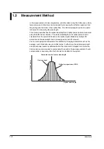
This section describes how the optical wavelength and optical power level are measured
using the FBG Sensor Monitor.  The center wavelength and its optical power level is

calculated from the power distribution of the optical signal obtained by multiple PD
elements and the wavelength that is pre-assigned to each PD element.

You can set appropriate measurement conditions by changing parameters such as the
average count, threshold value, and offset value.  Furthermore, the optical wavelength

and optical power level are calibrated before the instrument is shipped from the factory.
Commands are also provided to compensate the results of these measurements if such

compensation is necessary after the instrument is installed in the system.

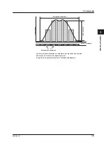
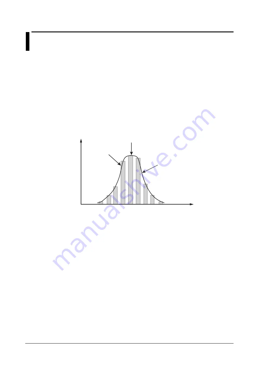
Computed result of center wavelength

Reflection spectrum of FBG

Optical wavelength

Device output

Optical po

wer

Содержание FB200

Страница 1: ...User s Manual Yokogawa Electric Corporation FB200 FBG Sensor Monitor IM 703753 01E 1st Edition ...

Страница 2: ...s However should you have any questions or find any errors please contact your nearest YOKOGAWA dealer Copying or reproducing all or any part of the contents of this manual without the permission of Yokogawa Electric Corporation is strictly prohibited This product s warranty is limited to its performance and functions Yokogawa shall not be responsible for any loss damage costs or expenses which ma...

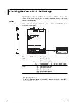
Страница 3: ...ODEL NO SUFFIX Made in Japan MODEL NO SUFFIX Made in Japan Model Suffix Code Description 703753 FBG Sensor Monitor D1 Standard specifications CN1 Optical connector FC type W1 Wavelength range 1 1527 to 1567 nm FB200C C band CN2 Wavelength range 2 1568 to 1607 nm FB200L L band Options IMJ User s manual Japanese IME User s manual English IM0 No user s manual DSJ Inspection report Japanese DSE Inspec...

Страница 4: ... If you are using the 703781 Power Supply Unit with the FB200C FB200L be sure to employ protective earth ground by connecting a power cord with a three prong plug with an earth pin to a properly grounded three pin outlet Do Not Operate with Defective Protective Grounding or Fuse Do not operate the instrument when the protective grounding or fuse of the instrument or the connected device might be d...

Страница 5: ... An error code list of measurement signals are also provided 5 Specifications Lists the specifications of the instrument the operating environment and other information in tables 6 Sample Program Provides a basic program example used to determine two peaks Index and Terminology Conventions Used in This Manual Unit k Denotes 1000 Example 9 6 kbps Safety Markings The following marking is used in thi...

Страница 6: ...nector 2 2 2 3 Installing the Instrument 2 3 Chapter 3 Operating Procedure 3 1 Setting the Mode Switch 3 1 3 2 Commands 3 2 3 3 Output Format 3 6 3 4 Using the FB200C FB200L through a PC 3 7 Chapter 4 Troubleshooting and Maintenance 4 1 Troubleshooting 4 1 4 2 Error Codes 4 2 4 3 Maintenance 4 4 Chapter 5 Specifications 5 1 Basic Specifications 5 1 5 2 General Specifications 5 2 5 3 Environmental ...

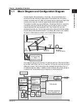
Страница 7: ...onsisting of 640 photodiode elements The optical system is fixed in place welded if necessary to endure vibration and shock and to minimize deterioration with age Photodiode array Mirror Shutter Fixed grating Signal processing and communication section Input fiber FC PC connector Depolarizer The configuration diagram is shown below The reflection spectrum of FBG that is detected by the optical sys...

Страница 8: ...al power level is calculated from the power distribution of the optical signal obtained by multiple PD elements and the wavelength that is pre assigned to each PD element You can set appropriate measurement conditions by changing parameters such as the average count threshold value and offset value Furthermore the optical wavelength and optical power level are calibrated before the instrument is s...

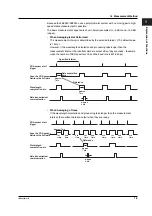
Страница 9: ...le when the number of FBG spectra is 10 and the baud rate is 921 6 kbps PDA sensor start trigger Wavelength computation etc Approx 7 ms Data transmission communication Scan the PDA sensor Retrieve the A D data Approx 7 ms Approx 2 ms Data acquisition time Specified interval Reference When Averaging n Times If the wavelength calculation and processing take longer than the measurement interval the r...

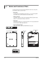
Страница 10: ...these switches Interface Connector The interface connector consists of the communication interface and power supply interface The communication interface is the RS 422 Optical Input The fiber light is applied here The optical connector is of an FC type standard and the fiber supports the SMF Single Mode Fiber Holes for Attachment Screws These holes are used to attach the FB200C FB200L in the syste...

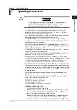
Страница 11: ...ion in the electrical circuit or contamination on the surface of the optical sensor leads to degrading of sensitivity may occur if the instrument is moved to another place where the ambient temperature is higher or if the temperature changes rapidly Use the instrument so that water droplets do not adhere to it Do not use the instrument in a dusty place Always attach the accessory cap after use Rem...

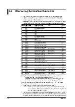
Страница 12: ...MOS 5 V input 24 GND 25 WDG Low during Watch Dog error Open collector OUT 26 GND 27 TMP Low during temperature Open collector OUT control error 28 BUSY Low during measurement Open collector OUT 29 WARMUP Low during warm up Open collector OUT 30 ERROR Low during other errors Open collector OUT The clock frequency is equal to 16 times the baud rate Note 1 The connector that is used is the FCN 705Q03...

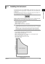
Страница 13: ... to 60 C Ambient humidity 5 to 85 RH no condensation Note To obtain highly accurate measurements operate the instrument in the 23 5 C temperature range Condensation may occur if the instrument is moved to another place where the ambient temperature is higher or if the temperature changes rapidly In such cases allow the instrument adjust to the new environment for at least one hour before using the...

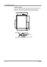
Страница 14: ...ure below When fastening the FB200C FB200L in place be sure that the attachment screws do not go deeper than 5 mm from the surface of the case 130 98 196 12 146 12 Holes for M3 attachment screws 6 locations 5mm or less FB200C FB200L case Panel for attaching the FB200C FB200L Attachment screw M3 2 3 Installing the Instrument ...

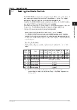
Страница 15: ...tra within the measurement conditions starting from the reflection spectrum with the highest optical power level up to the limit of the number of FBG reflection spectra FBG reflection spectra that exceeds the limit are not detected Selecting the Baud Rate Six baud rate settings are available By factor default the baud rate is set to 115 2 kbps Signal Name 9 6k bps SW1__8 SW1__7 SW1__6 SW1__5 SW1__...

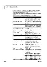
Страница 16: ...ry AVE Returns AVE_nn or AVI_nne Set the average count AVI_nne nne 101 to 503 100 times or more nne 203 20 103 20000 times Each average operation takes approximately 7 seconds The default value is 101 100 times Query AVI Returns AVInne or AVE_nn Zero calibration ZER Closes the shutter and performs zero measurement for each range The response time is approximately 13 seconds Returns OK ZER when the...

Страница 17: ...s when the average count is large the specified interval is ignored The default value is 10 ms The selectable range is 10 to 990 ms in 10 ms steps Query TIM Returns TIM_nnn or TIS_nnn Set the interval TIS_nnn Sets the measurement interval in unit of seconds 1 s or more nnn 060 60 s intervals Returns OK TIS_nnn when the process is complete The default value is 1 s The selectable range is 1 to 360 s...

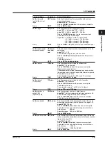
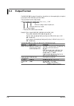
Страница 18: ...alue and the wavelength of the element exceeding the threshold level ZER_n nnn nnnnnn n Number of elements exceeding the threshold level 0 signifies that there are no elements that exceed the threshold level Data for up to 10 elements is output even if more than 10 elements exceed the threshold nnn Dark current value nW nnnnnn Wavelength nm Data assigned to the element wavelength offset Approximat...

Страница 19: ...er Photodiode array element Computation bandwidth Peak condition Set the computation bandwidth to a value that covers the ends of the spectrum However do not let it cover the adjacent spectrum The guide line is approximately twice the Full Width Half Maximum 3 2 Commands ...

Страница 20: ...6 24 dBm respectively The second center wavelength and power level are 1557 987 nm and 15 76 dBm respectively The detected FBGs are output in order from the shortest wavelength Response Data Format Description Response format BPM_nnn followed by the nnn 040 Transmit values of 40 waveforms For measured values of each the number of detected waveforms peak for nnn waveforms Example BPM_nnn nnnnnnn nn...

Страница 21: ...a obtained by applying a reference wavelength Communication command OFF_nnnn Optical Power Level Compensation P Optical power level compensation is performed by sending to the FB200C FB200L the compensation data for the optical power loss caused by the connection of the optical connector and other factors Communication command UPR_nnn nnn nnn nnn Threshold Level for FBG Sensor Detection Detects Se...

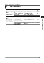
Страница 22: ...s after turning on the power Dusty or dirty optical connector Clean the optical connector 2 1 The FB200C FB200L is The FB200C FB200L case is not Ground the FB200C FB200L case to the 2 2 reset during operation due connected properly to the ground system s frame ground to noise Cannot change settings or The settings of the RS 422 Match the communication parameters 3 1 to 3 5 control the operation of...

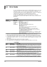
Страница 23: ...d when the error response is received The alarm from the signal pin is also cleared 2 You can determine whether the dark current from the PDA sensor exceeded the threshold level by sending the ZER communication command You can use this command to detect the presence or absence of PDA sensor errors 3 Error 8 is automatically cleared when the error response is received 4 If the measurement is not co...

Страница 24: ...If the error is output even after making the change decrease the input power to the FB200C FB200L n 7 1 PDA sensor Output when the PDA sensor has The FB200C FB200L has malfunctioned operation error deteriorated Accurate measurement is not possible dark current Request for repairs over the limit n 8 Computation Output when computation is not possible The FB200C FB200L has malfunctioned parameter er...

Страница 25: ...UTION The instrument will be repaired by a dedicated service personnel who is familiar with the construction of the instrument Do not open the instrument s cover without permission If you do we may not be able to repair it Maintaining the Performance The wavelength and optical power level are calibrated before this instrument is shipped from the factory To maintain the performance over an extended...

Страница 26: ...ess Total power of all spectra power Measurement characteristics Number of About 40 When FBGs are used at 1 nm measurable FBGs spacing between FWHM and 0 25 nm FBG spacing Approx 1 0 nm Smaller spacing is possible but should be twice FWHM Measurement 10 ms 100 Hz minimum Selectable range interval 10 ms to 990 ms in 10 ms steps 1 s to 360 s Example of conditions when measuring at 10 ms intervals Lo...

Страница 27: ...nnector External dimensions 170 W 28 H 220 D mm excluding protrusions Weight 1 5 kg or less Installation Rigid mount on an attachment frame using screw tightening torque of 0 6 N m Absolute Maximum Ratings Item Specifications Maximum supply voltage 0 3 to 6 5 V rating 5 V Maximum input power 10 dBm CW light 1 waveform 20 dBm CW light all input Miscellaneous Item Specifications Flame resistance Wir...

Страница 28: ...m s2 0 5 G during operation 9 8m s2 1 0 G during storage Shock 30 G when not operating The operating temperature is taken to be the area within 0 to 60 C and 5 to 85 RH of the template whose high temperature end described in GR 63 CORE Issue1 Oct 1995 NEBS Requirements 4 1 2 equipment is increased to 60 C The temperature range in which the specifications are met is 0 to 50 C 5 0 10 20 30 40 50 60 ...

Страница 29: ...ternal Dimensions 703753 D1 146 170 2 9 1 9 12 63 130 98 196 12 237 5 230 220 1 9 28 10 Unit mm Unless otherwise specified tolerance is 3 however tolerance is 0 3 mm when below 10 mm Holes for M3 attachment screws 6 locations ...

Страница 30: ...ed to be integrated into an FBG system device This chapter gives a connection setup and configuration example Line Settings Receive CR Send CR LF Port Settings Port See the setting of your PC Baud rate Set the required baud rate Number of data bits 8 bits Parity even Number of stop bits 1 bit Flow control Xon Xoff ...

Страница 31: ...ription Initialize setup RES OK RES parameters Select the range RNG_ 15 OK RNG_ 15 15 dBm range Set the average AVE_08 OK AVE_08 count Average count of 8 Set the BTH_ 1025 2025 3025 4025 OK BTH_ 1025 2025 3025 4025 threshold level Range Threshold 5 dBm 10 25 dBm 15 dBm 20 25 dBm 25 dBm 30 25 dBm 35 dBm 40 25 dBm Set the interval TIM_080 OK TIM_080 measurement at 80 ms intervals Continuous BPR BPM_...

Страница 32: ...interface connector 1 4 2 2 interval setting of 3 3 M maintenance 4 4 measurement interval 1 3 3 3 5 1 measurement method 1 2 measurement sequence 1 3 mode switch 1 4 MODEL ii N number of measured wavelengths 3 1 O OFF 3 2 operating humidity 5 3 operating temperature 5 3 optical input 1 4 optical wavelength offset compensation 3 7 output format 3 6 P PNM 3 3 peak condition 3 3 pin assignment 2 2 R...

Страница 33: ...Index 2 IM 703753 01E Index Z ZER 3 2 ZTH 3 2 ...

Страница 34: ...curacy Definition Absolute accuracy in wavelength measurement Readout resolution Definition The minimum change in the measured amount that can be read Optical input power Readout resolution Definition The minimum change in the measured amount that can be read Range switching Definition Range is defined by the minimum and maximum values of the input capacity or output capacity This means that there...

Страница 35: ...of 800 pm it is detected as a peak and the center wavelength is calculated Minimum power difference Maximum value 4 dB point from the maximum value 800pm Computation bandwidth Example If a point with a power difference of 4 0 dB does not exist within the computation bandwidth of 800 pm it is not detected as a peak Minimum power difference Maximum value 4 dB point from the maximum value 800pm Compu...

Отзывы: