4-2
IM 703753-01E
4.2
Error Codes
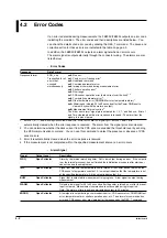
If an error is detected during measurements, the FB200C/FB200L outputs an error code
indicating the condition. The error codes and their descriptions are listed below. You
can check the details of an error code by sending the REA_7 command. The cause and
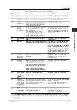
corrective action for these errors are indicated in the table on page 4-3.
In addition, the FB200C/FB200L outputs an alarm signal when an error occurs.
The alarm signal is output externally through the connector wiring. The alarms are also
listed below.
• Error Codes
Response
Data Format
Response format
ERR_n,n,n
n=0
: No error.
Transmitted for all
n=1
: Parity error or framing error
1
errors that
n=2
: Undefined command
occurred
n=3
: Command parameter error
simultaneously
n=4
: Improper command during measurement error
n=5
: Shutter operation error
1
n=6
: Over range
n=7
: PDA sensor operation error (dark current over the limit)
1, 2
n=8
: Computation parameter error
3
n=9
: Other hardware error (ROM/RAM error or temperature alarm)
1
n=A
: Warming up (cleared 30 to 40 seconds after the Power ON/Reset is
cleared in sync with the warm up output)
n=B
: Measurement interval overrun
4
The “other error alarm” signal pin is activated for 1, 5, 7, and 9 above. Errors 1
and 7 are cleared when the error response is received. The alarm from the
signal pin is also cleared.
1
Errors 1, 5, 7, and 9 are synchronized with the “other error alarm” signal pin. Errors 1 and 7 are
automatically cleared when the error response is received. The alarm from the signal pin is also cleared.
2
You can determine whether the dark current from the PDA sensor exceeded the threshold level by sending
the ZER communication command. You can use this command to detect the presence or absence of PDA
sensor errors.
3
Error 8 is automatically cleared when the error response is received.
4
If the measurement is not completed within the specified measurement interval, an error occurs.
• Alarm Signal
Signal
Output Level
Description
WDG_
Open Collector
Alarm by the internal watch dog timer. Set to low output during an error. If the output is
low, the internal processor has not finished the initialization procedure after startup or
cannot run due to some problem.
TMP_
Open Collector
Signal that monitors the temperature control status of the Peltier device that holds the
PDA sensor’s temperature constant. A low output indicates that the temperature is not
at the specified temperature. A high output indicates that it is.
BUSY_
Open Collector
Signal that is output while measurement is in progress. A low signal is output during
measurement.
WARM_
Open Collector
Outputs a low signal for 30 to 40 seconds after the power is turned on or after the reset
input is cleared. Measurement commands are not accepted during this period.
Note: The warm up time to achieve warranted accuracy is 30 minutes.
ERROR_
Open Collector
A low signal is output during a communication error, PDA sensor error, ROM/RAM test
error, temperature alarm, shutter operation error, etc. The alarms for communication
error and PDA sensor error are cleared after the response by the REA_7 command.

