


39
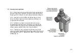
Distance between set scre
ws can not be less than table channel’s dimension. (Dimension of
TABLE CHANNEL is 7mm.)
7.2.3 Place the material to be cut on the table. By using the clamp button (FIG
URE 8 NO.18) on the control panel, fix
the material with the clamps, which are on the table. (FIGURE 2 NO 69)
)
7.2.4 Arrange the cutting degree of the material to be cut according to the scale (15-22.5-30-45-90) placed on the
machine. In order to rotate the rotating table (FIGURE 2 NO.95), loosen the table locked spring bolt (FIGURE 4
NO.53) by turning it counterclockwise. Fix the rotating table by bringing it to the degree that you wish to work at
with the help of the setting spring (FIGURE 4 NO.49). Finally, turn the table locked spring bolt clockwise and
tighten the table.
7.2.5 Switch the system start sw
itch to “1” (FIGURE 2 – NO.19)
7.2.6 Provide the saws to rotate by pressing the motor start buttons on the control panel.(FIGURE 8 NO.17)
7.2.7
Two hand safety by pressing buttons
(FIGURE 8 NO.15)
at the same time it will make upthe saw
.
and then
continue to press the buttons until the working part is cut.
7.2.8 After the end of cutting action, remove the hand pressure on the button. Both of the saws will come to the initial
position.
7.2.9 Release the clamps and remove the cut work piece.
7.2.10 Use the motor stop button to stop the saw rotation.
NOT: Remove the pressure on the cutting buttons in a possible hazard, or press the emergency stop
button.
7.2.11
Switch the system start switch to “0” (FIGURE 2 – NO.19)
Содержание ACK 420
Страница 4: ...4 BOYUTLAR DIMENSIONS РАЗМЕРЫ RESİM FIGURE РИСУНОК 1 ...
Страница 5: ...5 KESME DİYAGRAMI CUTTING DIAGRAM ДИАГРАММА РЕЗКИ ...
Страница 6: ...6 PARÇA LİSTESİ PART LIST ПЕРЕЧЕНЬ ДЕТАЛЕЙ RESİM FIGURE РИСУНОК 2 RESİM FIGURE РИСУНОК 3 ...
Страница 7: ...7 RESİM FIGURE РИСУНОК 4 RESİM FIGURE РИСУНОК 5 ...
Страница 8: ...8 RESİM FIGURE РИСУНОК 6 ...
Страница 9: ...9 RESİM FIGURE РИСУНОК 8 RESİM FIGURE РИСУНОК 7 RESİM FIGURE РИСУНОК 9 ...


