38
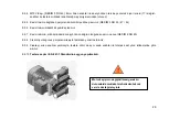
During cutting speed adjustment, be sure that the up clamping devices are out of working area.
(FIGURE 10)
7.2 Operation
..
7.2.1 If the profile to be cut is wide or high, loosen the M8 bolts (FIGURE 7 NO.34) on the square (FIGURE 7 NO.58)
and move them until you reach the backstop pins (FIGURE 7 NO 63). Limit of backwards movement is 100 mm.
Look at the cutting diagram for the maximum measurements and positions of the materials to be cut. Fix the
square (FIGURE 7 NO.58) to the table by tightening the M8 bolts.
7.2.2 In order to enable movement of the moving square to the right and left (FIG
URE 7 NO.65) loosen the fixing pipe
(FIGURE 7 NO.61) by turning it half a round. After movement of the moving square to the right or left direction,
with the help of the stay bolts on the fixed square (FIGURE 7 No.58), enable both moving squares to be parallel
to each other. After completing all the settings, tighten the fixing pipes and fix the squares.
FIGURE 10
Содержание ACK 420
Страница 4: ...4 BOYUTLAR DIMENSIONS РАЗМЕРЫ RESİM FIGURE РИСУНОК 1 ...
Страница 5: ...5 KESME DİYAGRAMI CUTTING DIAGRAM ДИАГРАММА РЕЗКИ ...
Страница 6: ...6 PARÇA LİSTESİ PART LIST ПЕРЕЧЕНЬ ДЕТАЛЕЙ RESİM FIGURE РИСУНОК 2 RESİM FIGURE РИСУНОК 3 ...
Страница 7: ...7 RESİM FIGURE РИСУНОК 4 RESİM FIGURE РИСУНОК 5 ...
Страница 8: ...8 RESİM FIGURE РИСУНОК 6 ...
Страница 9: ...9 RESİM FIGURE РИСУНОК 8 RESİM FIGURE РИСУНОК 7 RESİM FIGURE РИСУНОК 9 ...


