16
GB
O R I G I N A L I N S T R U C T I O N S
Operate power tool by insulated grasping surfaces, when performing an operation where the cutting accessory may
contact hidden wiring or its own cord.
Cutting accessory contacting a “live” wire may make exposed metal parts of the power
tool “live” and could give the operator an electric shock.
Wear hearing protection when diamond drilling.
Exposure to noise can cause hearing loss.
When the bit is jammed, stop applying downward pressure and turn o
ff
the tool.
Investigate and take corrective actions to
eliminate the cause of the bit jamming.
When restarting a diamond drill in the workpiece check that the bit rotates freely before starting.
If the bit is jammed, it may
not start, may overload the tool, or may cause the diamond drill to release from the workpiece.
When securing the drill stand with anchors and fasteners to the workpiece, ensure that the anchoring used is capable of
holding and restraining the machine during use.
If the workpiece is weak or porous, the anchor may pull out causing the drill
stand to release from the workpiece.
When drilling through walls or ceilings, ensure to protect persons and the work area on the other side.
The bit may extend
through the hole or the core may fall out on the other side.
Do not use this tool for overhead drilling with water supply.
Water entering the power tool will increase the risk of electric shock.
USE OF THE PRODUCT
Preparation for the operation.
Unpack the product and remove all elements of the packaging. It is recommended to keep the package for storage and transport
of the product. Check product in terms of damages, which could occur during the transport.
Note! Before commence of any preparatory works make sure that the switch key of the product is at the o
ff
position and
that the product is unplugged from the socket.
The drill rig can be prepared in two variants of operation: manual and on the rack.
If only it is possible use the rack since it makes operation simpler and safer.
Preparation for manual operation
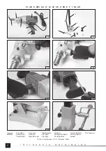
Insert the bracket of the additional grip into the front of the drill rig’s body and set it in such a way that the hole in the bracket covers
one of the holes in the body and secure it by tightening the screw (II). The ring must not move. Tighten the additional grip into the
bracket’s socket (III). Such a setting of the main grip and the additional grip is recommended to drill horizontally and at places
where space is limited. It requires higher counteracting power preventing unexpected turn of the drill rig.
The additional grip can be also directly tightened into the body opposite to the main grip (IV). Such a setting of the main grip and
the additional grip assures better control of the tool during the operation.
Next, install the rear support tightening it by means of screws to the rear part of the enclosure (V).
Preparation for operation on the rack
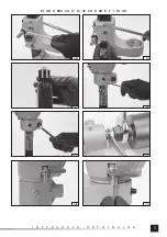
Base of the rack must be
fi
xed to the
fl
oor. Four holes in corners of the base are intended for this (VI). Use all of the holes to
fi
x
the rack to the base. Before commence of installation select proper type of the
fl
oor. Floor intended for installation must be solid
and of uniform structure. Loose and bulk
fl
oors such as stone or sand are not permitted. Connecting elements must be adjusted
to the
fl
oor; one can use raw plugs, anchors, screws and other screwed connecting elements. Do not use hammered connecting
elements. Forces produced during drilling can pull out such connecting elements from the
fl
oor. Moreover, base of the rack is
made from light alloys and it has not been designed to transfer loads occurring when connecting elements are hammered. The
base, after it has been
fi
xed to the
fl
oor, can be used in any position.
Install the wheel of the movable head of the rack. The wheel can be installed on one or the other side of the spindle of the head.
Insert the wheel on the spindle and tighten the screw it in such a way that the wheel is not able to leave the spindle.
Regulate resistance of the head of the rack. To do this one needs to use two screws and the wheel. Using screws regulate a con-
stant resistance. The wheel is used to increase the resistance. Loose slightly the counter nuts and then tighten the screws (VIII)
and protect their position by tightening the counter nuts. Tighten the wheel (IX) in order to increase the resistance and untighten
it in order to reduce the resistance.
Note! The wheel and screws are not intended to block the head’s movement totally. Resistance of the move must be adjusted in
such a way to assure the head does not change location when loaded by the drill rig installed in the head, and to assure smooth
movement of the head by means of the wheel.
Tighten the plug (X) into the hole at the peak of the column of the rack.
In case there is already installed a ring of the additional grip, dismount it. Dismount also the additional grip if it was tighten directly
into the body. The rear support is not necessary to work at the rack. However, if it is installed and it does not generate any prob-
lems to use the drill rig at the rack it does not have to be dismounted.
The drill rig must be installed in the head of the rack by inserting it into the bracket of the head. Then turn it till one of the holes
in the body covers a hole in the bracket and then secure the drill rig by tightening the screw (XI). Tighten the bracket by means
of the screw (XII).
Содержание YT-81980
Страница 26: ...26 RUS residual current device RCD...
Страница 27: ...27 RUS...
Страница 28: ...28 RUS II III IV V VI VII VIII IX X XI XII XIII...
Страница 29: ...29 RUS XIV XV XVI TEST RESET TEST RESET 30...
Страница 30: ...30 RUS XVII 0 3 MPa...
Страница 32: ...32 UA residual current device RCD...
Страница 33: ...33 UA II III...
Страница 34: ...34 UA IV V VI VII VIII IX X XI XII XIII XIV XV...
Страница 35: ...35 UA XVI TEST RESET TEST RESET 30...
Страница 36: ...36 UA XVII 0 3 MPa...
Страница 95: ...95 GR RCD RCD...
Страница 96: ...96 GR OFF...
Страница 97: ...97 GR II III IV V VI VII VIII IX X XI XII XIII...
Страница 98: ...98 GR XIV XV XVI PRCD OFF TEST PRCD PRCD RESET LED TEST PRCD OFF RESET 30...
Страница 99: ...99 GR o XVII 0 3 MPa...

