


5-33
n001 : Parameter Selection / Initialization
Factory setting: 1
Range: 0 to 9
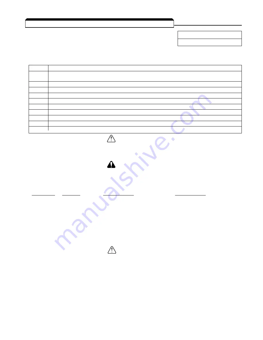
The following table shows which parameters can be programmed (displayed & changed) or only
displayed when n001 is selected.
Entering a “5” into n001 will allow a RUN command to be accepted even if the drive
is in Program mode (PRGM function LED on) or the LO/RE function LED is on. This condition
may cause the motor to run; equipment damage or personal injury may result.
By entering a “10” or an “11” into n001, all parameters in the Drive
will return to their factory settings.
Factory Configuration for
Parameter
Terminal
2-Wire Control
3-Wire Control
n050
S1
1 = Forward Run
1 = Start
n051
S2
2 = Reverse Run
2 = Stop
n052
S3
3 = External Fault (N.O.)
0 = Fwd/Rev Command
n053
S4
5 = Fault Reset
5 = Fault Reset
n054
S5
6 = Multi Step Ref. Cmd. A
6 = Multi Step Ref. Cmd. A
n055
S6
7 = Multi Step Ref. Cmd. B
7 = Multi Step Ref. Cmd. B
n056
S7
10 = JOG Selection
10 = JOG Selection
Know your application before using either Initialization function of n001 .
This parameter must be set to " 0 " to " 5 " for operation.
" 10 " = Factory 2-Wire Control Initialization (Maintained RUN Contact)
" 11 " = Factory 3-Wire Control Initialization (Momentary START/STOP Contact)
Entering either Initialization code resets all parameters to factory settings, and
automatically returns n001 setting to " 1 ". If the Drive is connected for 3-Wire
control and this parameter is set to " 10 " (2-Wire Control Initialization), the motor
may run in reverse direction WITHOUT A RUN COMMAND APPLIED. Equipment
damage or personal injury may result.
IMPORTANT
After " 10 " or " 11 " has been entered in n001 , the Motor Rated Current (n036 )
MUST BE REPROGRAMMED to the correct setting for the application.
5.21 RESET CODES: 2-WIRE, 3-WIRE INITIALIZATION
Setting
Function
0
n001 can be read and set;
n002 - n179 read only
1
n001 - n039 can be read and set
2
n001 - n067 can be read and set
3
n001 - n113 can be read and set
4
n001 - n179 can be read and set
5
n001 - n179 can be read and set – Run Command accepted during Program Mode
6
Clear Fault Record Only
7
Not Used
10
Initialization: 2-Wire control
11
Initialization: 3-Wire control
WARNING
CAUTION
CAUTION
Содержание SI-T/ V7
Страница 1: ...V7 and V74X Drives Technical Manual Models MV and CIMR V7 Document Number TM V7 01...
Страница 16: ...xiv Intentionally Left Blank...
Страница 18: ...xvi...
Страница 22: ...1 4 Continued 1 3 PHYSICAL INSTALLATION Figure 1 1b Component Identification...
Страница 31: ...1 13 Continued 1 4 ELECTRICAL INSTALLATION Figure 1 4 Installation of Line Filter and V7 Drive...
Страница 36: ...1 18...
Страница 48: ...3 2...
Страница 52: ...4 4...
Страница 97: ...5 45 PID Block Diagram 5 28 PID CONTROL Continued...
Страница 120: ...6 10...
Страница 128: ...A1 8...
Страница 132: ...A3 2...
Страница 144: ...A6 6...
Страница 148: ...A7 4...
Страница 152: ...A8 4...
Страница 156: ...I 4...


