Allowable load for wrist axis and wrist flange
7
-
40
7.4
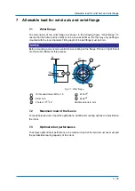
Allowable Wrist Load
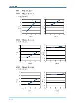
Fig. 7-2: Moment of arm rating
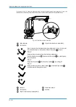
In order to facilitate the user's system applications , the peripheral equipment mounts and
tapped holes are provided on the wrist unit Fig. 7-3: "Installing peripheral equipment
mounts".
The following conditions should be observed to attach or install peripheral equipment Tab.
7-1: "Installation Conditions".
Fig. 7-3: Installing peripheral equipment mounts
P-point
B-axes rotation center line
R-, T-axes rotation center line
All dimensions in mm
View A
6 threaded holes M6 x 15
Section B-B
2 threaded holes M6 x 15
All dimensions in mm
200
800 600 400
200
400
600
800 1000
1
3
2
1000
200
400
600
800
1000
LB (mm)
LT (mm)
W=300 kg
W=250 kg
W=200 kg
1
3
2
20
122
20
20
177,5
122,5
30
53
B
B'
A
1
2
3
4
Ø 53
1
3
2
4
Содержание MPL300-J00
Страница 1: ...ROBOTICS MPL300 J00 YR MPL0300 J00 Operating and Maintenance Manual ...
Страница 61: ...Maintenance and inspection 9 61 Air outlet cap Joint 80 9 0 170 1 1 2 2 2 1 2 ...
Страница 91: ...Parts lists 11 91 ...
Страница 92: ...YASKAWA Headquarter ...


