FEATURES
1-5
• If the ERS indicator does not return to normal.
(Refer to “ELECTRONICALLY ADJUSTABLE
SUSPENSION SYSTEM (for YZF-R1M)” on
page 9-29.)
GPS indicator (CCU-equipped models)
This icon comes on when a GPS unit is synched
with your vehicle.
Logging indicator (CCU-equipped models)
This icon comes on when vehicle data is being
recorded via the logging function.
Clock
The clock uses a 12-hour time system.
Lap timer
This stopwatch function measures and records
up to forty laps. On the main screen, the lap tim-
er shows the current lap time and lap number
(indicated by the LAP mark). Use the Pass/LAP
switch to mark lap times. When a lap is complet-
ed, the lap timer will show the latest lap time
(marked by the LATEST indicator) for five sec-
onds.
[To use the lap timer]
1. Short push the wheel switch. The information
display item will flash for five seconds.
2. While the information display item is flashing,
rotate the wheel switch upward. The lap timer
will flash for five seconds.
3. While the lap timer is flashing, long push the
wheel switch to activate the lap timer or stop
the lap timer.
4. When the lap timer has been activated, press
the Pass/LAP switch to start the lap timer.
TIP
• The engine must be running to use the lap tim-
er.
• Set the information display to FASTEST or AV-
ERAGE for additional lap time information.
• Accessing the MENU screen will automatically
stop the lap timer.
• Whenever the lap timer is stopped, the current
lap will not be recorded.
• The lap time record can be viewed and reset
from the MENU screen.
Warning icons
When an error is detected, the following error-re-
lated warning icons will then be viewable.
SCU trouble warning (YZF-R1M)
This icon appears if a problem is detected in the
front or rear suspension.
Auxiliary system warning
This icon appears if a problem is detected in a
non-engine-related system.
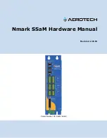
1. Lap time
2. Latest lap time indicator “LATEST”
3. Information display item
4. Lap number
N
12
12
3
4
LAP
01
ODO
12
3
456
LATE
S
T
1000 r/min
MPH
12
MPH
GEAR
GP
S
LC
S
Q
S
LIF
10:00
MODE-
A
PWR
1
TC
S
3
S
C
S
2
EBM
1
T-2
mile
2
3
4
1
2
1. SCU trouble warning “
”
2. Auxiliary system warning “
”
3. Coolant temperature warning “
”
4. Oil pressure warning “
”
5. Error mode warning “Err”
1000 r/min
4
1
2
5
3
Er r
Содержание YZF-R1
Страница 1: ...2020 SERVICE MANUAL YZF R1 YZF R1M YZFR1L YZFR1LC YZFR1ML YZF1MLC LIT 11616 33 33 B3L 28197 10 ...
Страница 2: ......
Страница 6: ......
Страница 8: ......
Страница 38: ...SPECIAL TOOLS 1 29 ...
Страница 55: ...TIGHTENING TORQUES 2 16 ...
Страница 58: ...CABLE ROUTING 2 19 Frame front right side view A B C D E F G H I J K L M 1 1 1 2 3 5 5 4 4 4 6 5 7 8 9 ...
Страница 60: ...CABLE ROUTING 2 21 Frame rear right side view B A C D 2 1 2 3 4 5 6 7 ...
Страница 76: ...CABLE ROUTING 2 37 Rear fender left side view A B C D G 1 2 3 4 5 6 7 7 8 8 7 10 10 11 E 2 9 3 3 9 F 3 ...
Страница 82: ...CABLE ROUTING 2 43 Front brake hose left side view A 1 1 1 1 2 2 2 3 3 3 4 4 4 3 4 ...
Страница 84: ...CABLE ROUTING 2 45 Hydraulic unit assembly top and left side view A B C 1 2 3 3 4 4 5 6 7 7 8 8 9 10 10 11 11 ...
Страница 86: ...CABLE ROUTING 2 47 Fuel tank top and left side view A B 1 2 3 4 5 2 5 ...
Страница 88: ...CABLE ROUTING 2 49 Canister for California A E 1 2 3 4 5 6 B B B C D 7 8 9 10 E F G H E 7 10 11 ...
Страница 92: ...CABLE ROUTING 2 53 Air cut off valve right side view A B C C D E 1 2 2 3 3 3 4 4 5 5 5 6 7 ...
Страница 96: ...CABLE ROUTING 2 57 Radiator left side view A B C D E F G H I J G K L M N O 1 2 2 2 3 3 3 4 5 6 7 8 9 D ...
Страница 100: ...CABLE ROUTING 2 61 Muffler top and left side view 1 1 2 3 3 4 5 5 6 6 4 4 5 6 5 6 A ...
Страница 102: ...CABLE ROUTING 2 63 CCU top and right side view for YZF R1M A B C D E F G H 1 2 3 2 3 4 5 6 4 5 6 7 7 8 9 9 10 ...
Страница 104: ...CABLE ROUTING 2 65 ...
Страница 107: ......
Страница 144: ...PERIODIC MAINTENANCE 3 37 ...
Страница 149: ......
Страница 171: ...GENERAL CHASSIS 5 4 22 T R Front muffler protector bolt 7 N m 0 7 kgf m 5 2 lb ft b b a a 1 ...
Страница 222: ...REAR BRAKE 4 73 6 Adjust Rear brake light operation timing Refer to ADJUSTING THE REAR BRAKE LIGHT SWITCH on page 3 35 ...
Страница 280: ...CHAIN DRIVE 4 131 ...
Страница 336: ...ELECTRIC STARTER 5 53 1 2 3 a b ...
Страница 406: ...WATER PUMP 6 17 ...
Страница 432: ...AIR INDUCTION SYSTEM 7 25 ...
Страница 435: ......
Страница 441: ...IGNITION SYSTEM 8 6 ...
Страница 449: ...CHARGING SYSTEM 8 14 ...
Страница 453: ...LIGHTING SYSTEM 8 18 ...
Страница 488: ...ELECTRICAL COMPONENTS 8 53 ...
Страница 496: ...89_ABS 9 295 TROUBLESHOOTING 9 295 90_ABS 9 298 TROUBLESHOOTING 9 298 91_ABS 9 301 TROUBLESHOOTING 9 301 ...
Страница 497: ......
Страница 507: ...SYSTEM DIAGRAM 9 10 ...
Страница 525: ...STEERING DAMPER SYSTEM 9 28 ...
Страница 800: ...91_ABS 9 303 4 Defective hydraulic unit assembly Replace the hydraulic unit assembly ...
Страница 801: ...91_ABS 9 304 ...
Страница 804: ......
Страница 805: ......
Страница 806: ......