


2 - 52
SPEC
Í
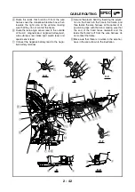
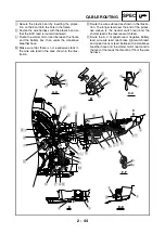
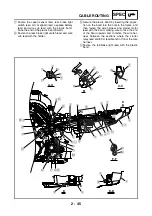
Secure the plastic band by inserting the projec-
tion on the band into the hole in the frame, and
then fasten the leads where the throttle position
sensor lead branches off from the other leads,
making sure to face the end of the band rear-
ward.
Î
From the left side of the vehicle
Ï
Install the hose (air filter joint to right side of
throttle body) onto the pipe on the air filter joint.
Ð
Route the leads that branch off from the wire
harness over the fast idle plunger outlet hose
and to the right of the hose (air filter joint to right
side of throttle body).
Ñ
Route the fuel injector lead over the intake air
pressure sensor.
Ò
Route the headlight lead over the frame, con-
nect the headlight coupler, and then insert the
projection on the coupler into the hole in the stay
on the front fender bracket.
‘
Ë
Ì
Í
Ï
Ð
Ñ
E
F
G
B
C
D
A-A
I-I
A
A
C
E
G
D
F
I
I
K
K
4
6
5
3
L
N
3
M
L
P
H
H
7
8
J
2
1
H
G
F
D
E
C
B
A
0
I
I
I
I
J
J
J
A
0
7
J
O
5
6
4
3
Õ
Ò
Ó
Ö
È
É
3
4
Î
Ê
O
Ô
5
6
9
B
Содержание YFM700RV 2009
Страница 1: ...YFM700RV SERVICE MANUAL 1S3 28197 E0 ...
Страница 34: ...2 11 SPEC ENGINE SPECIFICATIONS Cylinder head tightening sequence 1 3 2 4 5 7 8 6 ...
Страница 52: ...2 29 SPEC OIL FLOW DIAGRAMS 1 Oil delivery pipe 2 Oil filter 3 Oil pump 2 3 A A A A 2 1 ...
Страница 55: ...2 32 SPEC OIL FLOW DIAGRAMS 1 Balancer 1 2 Crankshaft 2 1 ...
Страница 408: ...YAMAHA MOTOR CO LTD 2500 SHINGAI IWATA SHIZUOKA JAPAN ...