


6 - 7
FI
EAS00905
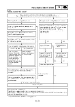
DIAGNOSTIC MODE
It is possible to monitor the sensor output data
or check the activation of actuators with the FI
diagnostic tool connected to the vehicle and
set to the normal mode or the diagnostic moni-
toring mode.
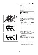
Setting the normal mode
NOTE:
_
The engine speed, engine temperature, and
fault code, if detected, can be displayed on the
LCD of the FI diagnostic tool when the tool is
connected to the vehicle and is set to the nor-
mal mode.
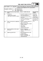
1. Turn the main switch to “OFF” and set the
engine stop switch to “RUN”.
2. Remove the self-diagnosis signal coupler
cap, and then connect the FI diagnostic tool
1
as shown.
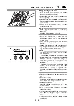
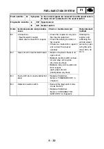
3. Turn the main switch to “ON” and start the
engine.
NOTE:
_
• Coolant temperature and engine revolution
appear on the LCD of the FI diagnostic tool.
• “POWER” LED (Green) comes on.
• If a malfunction is detected in the system,
“WARNING” LED (Orange) comes on.
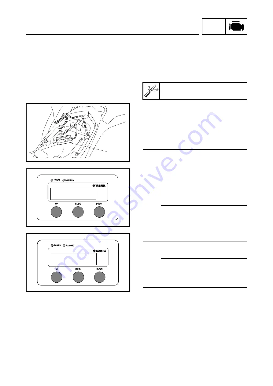
4. Stop the engine.
NOTE:
_
If a malfunction is detected in the system, the
fault code appears on the LCD of the FI diag-
nostic tool. And also, “WARNING” LED
(Orange) comes on.
5. Turn the main switch to “OFF” to cancel the
normal mode.
6. Disconnect the FI diagnostic tool and con-
nect the self-diagnosis signal connector.
FI diagnostic tool
90890-03182, YU-03182
1
FI Diagnostic Tool
1600rpm 35˚C
FI Diagnostic Tool
0rpm 35˚C
S/D : 12
Содержание YFM700RV 2009
Страница 1: ...YFM700RV SERVICE MANUAL 1S3 28197 E0 ...
Страница 34: ...2 11 SPEC ENGINE SPECIFICATIONS Cylinder head tightening sequence 1 3 2 4 5 7 8 6 ...
Страница 52: ...2 29 SPEC OIL FLOW DIAGRAMS 1 Oil delivery pipe 2 Oil filter 3 Oil pump 2 3 A A A A 2 1 ...
Страница 55: ...2 32 SPEC OIL FLOW DIAGRAMS 1 Balancer 1 2 Crankshaft 2 1 ...
Страница 408: ...YAMAHA MOTOR CO LTD 2500 SHINGAI IWATA SHIZUOKA JAPAN ...