CABLE ROUTING
2-28
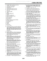
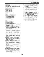
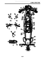
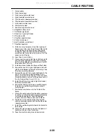
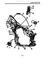
1. Clutch cable
2. Starter cable
3. Air induction system hose (from air filter case to
air cut-off valve)
4. Cylinder head breather hose
5. Sidestand switch lead
6. Speed sensor lead
7. Neutral switch lead
8. Stator assembly lead
9. Main switch lead
10. Meter assembly leads
11. Front brake hose
12. Throttle cable (decelerator cable)
13. Throttle cable (accelerator cable)
14. Right handlebar switch lead
15. Front brake light switch lead
16. Left handlebar switch lead
17. Clutch switch lead
18. Negative battery lead
19. Speed sensor
20. Rear turn signal light
21. Carburetor fuel drain hose
22. Rear turn signal light bracket
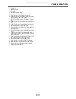
A. Each lead should not be exposed to the outside
of the front left sidecover.
B. Secure the left handlebar switch lead, clutch
switch lead, front left turn signal light lead, and
main switch lead using clamp. Face the clamp
opening downwards.
C. Pass the clutch cable through the guide.
D. Enter each lead from the cutout of front left
sidecover and run inside of the sidecover. Install
each lead above the clutch cable without slack.
E. Clamp the starter cable using plastic locking tie
and cut off the excess end of the tie. Face the
end of the tie downwards.
F. Pass the starter cable through the square
shape of air cut-off valve bracket, and route out-
side the air induction system hose (from air filter
case to air cut-off valve) and cylinder head
breather hose.
G. Secure the ignition coil lead, stator assembly
lead, sidestand switch lead, neutral switch lead,
and speed sensor lead using clamp. Face the
clamp opening upward.
H. Secure the sidestand switch lead to the frame
using clamps.
I. Secure the neutral switch lead and speed sen-
sor lead using clamp. Face the clamp opening
backward.
J. Secure the stator assembly lead using clamps.
The clamp opening should face downwards
away from the vehicle.
K. Secure the wire harness boot onto the guide.
L. Route the clutch cable above the cylinder head
breather hose.
M. Route the clutch cable at the rear of the guide.
N. Pass the ignition coil lead, stator assembly lead,
sidestand switch lead, neutral switch lead, and
speed sensor lead through the boot. Insert all
couplers into the boot.
O. Secure two carburetor air vent hoses, carbure-
tor fuel drain hose, and negative battery lead
using clamp. Face the clamp holders on the left
of the vehicle.
P. Pass the speed sensor lead between each
hose and the crankcase.
Q. Secure two carburetor air vent hoses, carbure-
tor fuel drain hose, and neutral switch lead
using clamp.
R. Secure the neutral switch lead using clamp.
S. Pass the rear turn signal light leads (left and
right) through the opening of rear turn signal
light bracket, and secure the leads using plastic
locking tie. Face the cable tie end inward, and
cut off the excess end of the tie.
T. Route the carburetor fuel drain hose through
the guide.
U. Route the carburetor fuel drain hose through
the rear of frame cross tube as shown in the
illustration.(Except for California)
V. Using plastic locking tie, secure the neutral
switch lead and speed sensor lead onto the
clamp as shown in the illustration.
All manuals and user guides at all-guides.com
Содержание XT250X 2008
Страница 2: ...All manuals and user guides at all guides com...
Страница 8: ...All manuals and user guides at all guides com...
Страница 50: ...CABLE ROUTING 2 31 A D C I H G 1 2 3 4 5 6 8 E L K M J B A A 7 F All manuals and user guides at all guides com...
Страница 54: ...CABLE ROUTING 2 35 All manuals and user guides at all guides com...
Страница 82: ...ELECTRICAL SYSTEM 3 27 a b All manuals and user guides at all guides com...
Страница 170: ...VALVES AND VALVE SPRINGS 5 24 All manuals and user guides at all guides com...
Страница 220: ...AIR INDUCTION SYSTEM 6 9 EAS27040 AIR INDUCTION SYSTEM 1 2 4 6 7 3 5 All manuals and user guides at all guides com...
Страница 224: ...AIR INDUCTION SYSTEM 6 13 All manuals and user guides at all guides com...
Страница 237: ...CHARGING SYSTEM 7 12 2 A C magneto 3 Rectifier regulator 4 Fuse 6 Battery All manuals and user guides at all guides com...
Страница 239: ...CHARGING SYSTEM 7 14 All manuals and user guides at all guides com...
Страница 243: ...LIGHTING SYSTEM 7 18 All manuals and user guides at all guides com...
Страница 249: ...SIGNALING SYSTEM 7 24 All manuals and user guides at all guides com...
Страница 253: ...CARBURETOR HEATING SYSTEM 7 28 All manuals and user guides at all guides com...
Страница 256: ...ELECTRICAL COMPONENTS 7 31 2 1 8 9 5 4 3 7 6 All manuals and user guides at all guides com a l l g u i d e s c o m...
Страница 279: ...All manuals and user guides at all guides com...
Страница 280: ...YAMAHA MOTOR CO LTD 2500 SHINGAI IWATA SHIZUOKA JAPAN PRINTED IN U S A All manuals and user guides at all guides com...

