background image

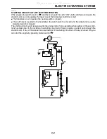
ELECTRIC STARTING SYSTEM

7-6

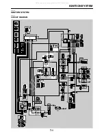
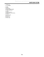
4.  Fuse
5.  Starter relay
6.  Battery
7.  Starter motor
8.  Diode 1
9.  Main switch
10. Right handlebar switch
11. Engine stop switch
12. Start switch
13. Diode 2
14. Clutch switch
15. Sidestand switch
16. Starting circuit cut-off relay
17. Diode 3
18. Neutral switch

All manuals and user guides at all-guides.com

all-guides.com

Содержание XT250X 2008

Страница 1: ...3C5 28197 10 XT250X XT250XC SERVICE MANUAL LIT 11616 21 52 2008 All manuals and user guides at all guides com a l l g u i d e s c o m...

Страница 2: ...All manuals and user guides at all guides com...

Страница 3: ...ation U S A First edition August 2007 All rights reserved Any reproduction or unauthorized use without the written permission of Yamaha Motor Corporation U S A is expressly prohibited Printed in U S A...

Страница 4: ...tomer with the most satisfaction from his vehicle and to conform to federal environmental quality objectives Yamaha Motor Company Ltd is continually striving to improve all of its models Modifications...

Страница 5: ...ng 1 17 Ball 1 18 Clutch push rod 1 19 Primary drive gear 1 For installation reverse the removal proce dure New New E T R 8 Nm 0 8 m kg 5 8 ft Ib T R 75 Nm 7 5 m kg 54 ft Ib T R 80 Nm 8 0 m kg 58 ft I...

Страница 6: ...le with engine mounted 2 Filling fluid 3 Lubricant 4 Special tool 5 Tightening torque 6 Wear limit clearance 7 Engine speed 8 Electrical data 9 Engine oil 10 Gear oil 11 Molybdenum disulfide oil 12 Br...

Страница 7: ...INFORMATION 1 SPECIFICATIONS 2 PERIODIC CHECKS AND ADJUSTMENTS 3 CHASSIS 4 ENGINE 5 FUEL SYSTEM 6 ELECTRICAL SYSTEM 7 TROUBLESHOOTING 8 EAS20110 TABLE OF CONTENTS All manuals and user guides at all gu...

Страница 8: ...All manuals and user guides at all guides com...

Страница 9: ...1 1 IMPORTANT INFORMATION 1 2 PREPARATION FOR REMOVAL AND DISASSEMBLY 1 2 REPLACEMENT PARTS 1 2 GASKETS OIL SEALS AND O RINGS 1 2 LOCK WASHERS PLATES AND COTTER PINS 1 2 BEARINGS AND OIL SEALS 1 2 CIR...

Страница 10: ...TION NUMBER The vehicle identification number 1 is stamped into the right side of the steering head pipe EAS20150 MODEL LABEL The model label 1 is affixed to the frame This information will be needed...

Страница 11: ...se oil and grease recommended by Yamaha for all lubrication jobs Other brands may be similar in function and appearance but inferior in quality EAS20210 GASKETS OIL SEALS AND O RINGS 1 When overhaulin...

Страница 12: ...c es EAS20240 CIRCLIPS Before reassembly check all circlips carefully and replace damaged or distorted circlips Al ways replace piston pin clips after one use When installing a circlip 1 make sure the...

Страница 13: ...3 Check All connections Loose connection Connect properly NOTE If the pin 1 on the terminal is flattened bend it up 4 Connect Lead Coupler Connector NOTE Make sure all connections are tight 5 Check Co...

Страница 14: ...stakes NOTE For U S A and Canada use part number starting with YM YU or ACC For others use part number starting with 90890 Tool name Tool No Illustration Reference pages Pocket tester 90890 03132 1 4...

Страница 15: ...890 01522 3 27 Cylinder cup installer 90890 01996 4 22 4 33 Damper rod holder 90890 01460 4 42 4 44 T handle 90890 01326 T handle 3 8 drive 60 cm long YM 01326 4 44 Fork seal driver weight 90890 01367...

Страница 16: ...pring compressor 90890 04019 YM 04019 5 18 5 23 Valve guide remover 6 90890 04064 Valve guide remover 6 0 mm YM 04064 A 5 20 Valve guide installer 6 90890 04065 Valve guide installer 6 0 mm YM 04065 A...

Страница 17: ...holder YS 01880 A 5 47 5 48 Flywheel puller 90890 01362 Heavy duty puller YU 33270 B 5 47 Yamaha bond No 1215 Three Bond No 1215 90890 85505 5 56 Crankcase separating tool 90890 01135 Crankcase separ...

Страница 18: ...Adapter M10 90890 01383 Adapter 2 YU 90062 5 60 Spacer 90890 01288 5 60 Ignition checker 90890 06754 Opama pet 4000 spark checker YM 34487 7 43 Digital circuit tester 90890 03174 Model 88 Multimeter...

Страница 19: ...RQUES 2 13 GENERAL TIGHTENING TORQUE SPECIFICATIONS 2 13 ENGINE TIGHTENING TORQUES 2 13 CHASSIS TIGHTENING TORQUES 2 15 LUBRICATION POINTS AND LUBRICANT TYPES 2 18 ENGINE 2 18 CHASSIS 2 19 LUBRICATION...

Страница 20: ...150 mm 84 6 in Overall width 805 mm 31 7 in Overall height 1160 mm 45 7 in Seat height 810 mm 31 9 in Wheelbase 1360 mm 53 5 in Ground clearance 285 mm 11 22 in Minimum turning radius 1900 mm 74 8 in...

Страница 21: ...23 Imp qt Without oil filter element replacement 1 20 L 1 27 US qt 1 06 Imp qt With oil filter element replacement 1 30 L 1 37 US qt 1 14 Imp qt Oil filter type Paper Oil pump Oil pump type Trochoid I...

Страница 22: ...24 0 4731 in Limit 12 036 mm 0 4739 in Rocker arm shaft outside diameter 11 981 11 991 mm 0 4717 0 4721 in Limit 11 950 mm 0 4705 in Rocker arm to rocker arm shaft clearance 0 009 0 037 mm 0 0004 0 00...

Страница 23: ...0 0012 in Cylinder head valve seat width intake 0 90 1 10 mm 0 0354 0 0433 in Limit 1 7 mm 0 07 in Cylinder head valve seat width exhaust 0 90 1 10 mm 0 0354 0 0433 in Limit 1 7 mm 0 07 in Valve sprin...

Страница 24: ...0 N mm 232 97 lb in 4 16 kgf mm Installed compression spring force intake 128 50 157 90 N 28 89 35 50 lbf 13 10 16 10 kgf Installed compression spring force exhaust 128 50 157 90 N 28 89 35 50 lbf 13...

Страница 25: ...el Dimensions B T 0 90 2 75 mm 0 04 0 11 in End gap installed 0 19 0 31 mm 0 0075 0 0122 in Limit 0 56 mm 0 0220 in Ring side clearance 0 030 0 065 mm 0 0012 0 0026 in Limit 0 115 mm 0 0045 in 2nd rin...

Страница 26: ...Clutch housing thrust clearance 0 100 0 350 mm 0 0039 0 0138 in Clutch housing radial clearance 0 010 0 044 mm 0 0004 0 0017 in Push rod bending limit 0 500 mm 0 0197 in Transmission Transmission typ...

Страница 27: ...0 8x1 2 Pilot jet 34 Bypass 1 0 8 Bypass 2 0 8 Bypass 3 0 8 Bypass 4 0 8 Pilot screw turn out 2 1 2 Valve seat size 0 50 Starter jet 1 90 Starter jet 2 78 Throttle valve size 33 Float height 11 9 mm 0...

Страница 28: ...re Type With tube Size 2 75 21 45P Manufacturer model CHENG SHIN C 6006 Manufacturer model DUNLOP D605F Wear limit front 0 8 mm 0 03 in Rear tire Type With tube Size 120 80 18M C 62P Manufacturer mode...

Страница 29: ...n Master cylinder inside diameter 12 7 mm 0 50 in Caliper cylinder inside diameter 30 23 mm 1 19 in Recommended fluid DOT 4 Steering Steering bearing type Taper roller bearing Center to lock angle lef...

Страница 30: ...190 W 5000 r min Stator coil resistance 0 688 1 032 White white Rectifier regulator Regulator type Semi conductor short circuit Model manufacturer SH629A 12 SHINDENGEN No load regulated voltage 14 1...

Страница 31: ...er 2768096 A JIDECO Amperage 180 0 A Coil resistance 4 18 4 62 Horn Horn type Plane Quantity 1 pcs Model manufacturer HF 12 NIKKO Maximum amperage 3 0 A Coil resistance 1 01 1 11 Performance 108 116 d...

Страница 32: ...4 mm 10 mm 30 3 0 22 17 mm 12 mm 55 5 5 40 19 mm 14 mm 85 8 5 61 22 mm 16 mm 130 13 0 94 Item Threa d size Q ty Tightening torque Remarks Camshaft sprocket cover bolt M6 2 10 Nm 1 0 m kg 7 2 ft lb Tim...

Страница 33: ...g 12 ft lb Oil pump cover screw M6 1 7 Nm 0 7 m kg 5 1 ft lb Oil pump assembly bolt M6 3 6 Nm 0 6 m kg 4 3 ft lb Air filter case bolt M6 3 7 Nm 0 7 m kg 5 1 ft lb Air cut off valve bolt M6 1 7 Nm 0 7...

Страница 34: ...ty Tightening torque Remarks Engine mounting nut M10 3 60 Nm 6 0 m kg 43 ft lb Engine bracket nut M8 2 44 Nm 4 4 m kg 32 ft lb Down tube nut M10 5 60 Nm 6 0 m kg 43 ft lb Drive chain tensioner bolt M...

Страница 35: ...bolt M6 2 7 Nm 0 7 m kg 5 1 ft lb Headlight unit bolt M6 2 7 Nm 0 7 m kg 5 1 ft lb Rear shock absorber assembly lower nut M10 2 40 Nm 4 0 m kg 29 ft lb Connecting arm bolt relay arm side M12 1 59 Nm 5...

Страница 36: ...ft lb Rear brake disc bolt M8 3 28 Nm 2 8 m kg 21 ft lb Front brake master cylinder holder bolt M6 2 7 Nm 0 7 m kg 5 1 ft lb Front brake lever nut M6 1 7 Nm 0 7 m kg 5 1 ft lb Rear brake hose joint ca...

Страница 37: ...pin surface Piston surface Buffer boss surface Valve stem intake exhaust Valve stem end intake exhaust Rocker arm shaft surface intake exhaust Camshaft profile Rocker arm inner surface intake exhaust...

Страница 38: ...ication point Lubricant Upper bearings and oil seal lip steering head Lower bearings and oil seal lip steering head Front wheel oil seal lip left right Rear wheel oil seal lip left right Brake pedal b...

Страница 39: ...shaft on the frame and connecting arm Relay arm bolt shaft Connecting arm bolt shaft Lower bolt shaft of rear shock absorber assembly Rear wheel axle surface Sidestand switch end and contact Frame an...

Страница 40: ...RICATION SYSTEM CHART AND DIAGRAMS 2 21 EAS20390 LUBRICATION SYSTEM CHART AND DIAGRAMS EAS20400 ENGINE OIL LUBRICATION CHART 6 7 8 2 4 10 1 5 11 9 1 2 3 4 5 All manuals and user guides at all guides c...

Страница 41: ...1 Camshaft 2 Oil filter element 3 Oil level check window 4 Oil pump assembly 5 Oil strainer 6 Drive axle 7 Main axle 8 Plunger pin 9 Crankshaft 10 Cylinder head 11 Oil pan All manuals and user guides...

Страница 42: ...LUBRICATION SYSTEM CHART AND DIAGRAMS 2 23 EAS20410 LUBRICATION DIAGRAMS 8 2 6 4 1 2 3 7 5 All manuals and user guides at all guides com...

Страница 43: ...ATION SYSTEM CHART AND DIAGRAMS 2 24 1 Crankshaft 2 Oil pump assembly 3 Oil strainer 4 Camshaft 5 Push lever shaft 6 Drive axle 7 Main axle 8 Oil filter element All manuals and user guides at all guid...

Страница 44: ...A A F F E E C C G D A B C D F E G H L J K M N O P R S Q T U V W X Y Z 1 3 3 3 4 5 6 7 8 8 9 11 10 10 12 13 22 21 13 15 13 14 20 16 16 17 18 19 19 AC AD AF AE AG AH AI AM AN AN AJ AB AA I 2 AF AK AL A...

Страница 45: ...he rear brake light switch lead using clamps Face the clamp opening inwards V Pass the rear brake light switch lead along the frame and install the rear brake light switch W Secure the rear brake ligh...

Страница 46: ...NG 2 27 D B A E C F A B C D E F G G H H I J K L M N O P Q Q R S V T U 1 2 3 4 5 6 P 6 6 7 7 8 9 11 10 12 13 14 15 16 17 18 19 20 22 21 V G O All manuals and user guides at all guides com a l l g u i d...

Страница 47: ...itch lead neutral switch lead and speed sensor lead using clamp Face the clamp opening upward H Secure the sidestand switch lead to the frame using clamps I Secure the neutral switch lead and speed se...

Страница 48: ...CABLE ROUTING 2 29 L J M N 3 4 5 6 16 N M A A C D E F F G H J I K 1 2 3 4 5 6 7 8 9 10 11 12 13 14 15 16 17 B B D C 3 4 5 6 15 15 16 F F E E 1 B All manuals and user guides at all guides com...

Страница 49: ...ame without slack E Secure the rear turn signal light leads left and right and tail brake light leads with clamp Face the clamp opening upwards F Secure the rear left turn signal light lead to the end...

Страница 50: ...CABLE ROUTING 2 31 A D C I H G 1 2 3 4 5 6 8 E L K M J B A A 7 F All manuals and user guides at all guides com...

Страница 51: ...and left handlebar switch as shown in the illus tration F To the headlight G Band the meter assembly leads handlebar switch leads left and right front brake light switch lead front turn signal light l...

Страница 52: ...CABLE ROUTING 2 33 C E G H 1 3 A A B D F E G L J K M N 3 4 I 2 G 2 B C D All manuals and user guides at all guides com...

Страница 53: ...ose to the guide G The clip may be installed which ever direction end of the clip H Pass through the canister breather hose to the guide I Install the end of the canister breather hose to inside of th...

Страница 54: ...CABLE ROUTING 2 35 All manuals and user guides at all guides com...

Страница 55: ...FRONT DISC BRAKE 3 16 ADJUSTING THE REAR DISC BRAKE 3 16 CHECKING THE BRAKE FLUID LEVEL 3 17 CHECKING THE FRONT BRAKE PADS 3 17 CHECKING THE REAR BRAKE PADS 3 18 CHECKING THE FRONT BRAKE HOSE 3 18 CHE...

Страница 56: ...changes EAS17580 Periodic maintenance chart for the emission control system No ITEM ROUTINE INITIAL ODOMETER READINGS 600 mi 1000 km or 1 month 4000 mi 6000 km or 6 months 7000 mi 11000 km or 12 month...

Страница 57: ...or replace cable 3 Front brake Check operation fluid level and for fluid leakage Replace brake pads if nec essary 4 Rear brake Check operation fluid level and for fluid leakage Replace brake pads if...

Страница 58: ...d grease lightly 18 Sidestand switch Check operation and replace if necessary 19 Front fork Check operation and for oil leakage Replace if necessary 20 Shock absorber assembly Check operation and for...

Страница 59: ...areas Hydraulic brake service After disassembling the brake master cylinders and calipers always change the fluid Regularly check the brake fluid levels and fill the reservoirs as required Every two...

Страница 60: ...plug cap Spark plug 4 Remove Timing mark accessing screw 1 Crankshaft end cover 2 5 Measure Valve clearance Out of specification Adjust a Turn the crankshaft counterclockwise b When the piston is in...

Страница 61: ...O ring Intake tappet cover 10 Install Fuel tank Refer to FUEL TANK on page 6 1 EAS20610 ADJUSTING THE ENGINE IDLING SPEED NOTE Before adjusting the engine idling speed the air filter element should b...

Страница 62: ...e engine idling speed should be adjusted properly 1 Check Throttle cable play a Out of specification Adjust 2 Adjust Throttle cable free play Carburetor side a Loosen locknut 1 of the pulling accelera...

Страница 63: ...ge wear Replace the spark plug Insulator 2 Abnormal color Replace the spark plug Normal color is medium to light tan 5 Clean Spark plug with a spark plug cleaner or wire brush 6 Measure Spark plug gap...

Страница 64: ...TE Insufficient compression pressure will result in a loss of performance 1 Measure Valve clearance Out of specification Adjust Refer to ADJUSTING THE VALVE CLEAR ANCE on page 3 5 2 Start the engine w...

Страница 65: ...tall Spark plug 8 Connect Spark plug cap EAS20730 CHECKING THE ENGINE OIL LEVEL 1 Stand the vehicle on a level surface NOTE Place the vehicle on a suitable stand Make sure the vehicle is upright 2 Sta...

Страница 66: ...utes and then turn it off 2 Place a container under the engine oil drain bolt 3 Remove Engine oil filler cap 1 Engine oil drain bolt 2 along with the gasket Oil filter element drain bolt 3 4 Drain En...

Страница 67: ...ff so that it will not seize c Check the engine oil passages the oil filter cartridge and the oil pump for damage or leakage Refer to INSTALL THE OIL PUMP AND BALANCER GEAR on page 5 41 d Start the en...

Страница 68: ...ement Also clean the air filter case and air fil ter check hose 2 Remove Seat Refer to GENERAL CHASSIS on page 4 1 3 Remove Air filter case cap 1 4 Check Air filter element 1 Damage obstruction Replac...

Страница 69: ...e 1 Vacuum hose Breather hose Cracks damage Replace Loose connection Connect properly or re place the clip hose 3 Install Left fuel tank side cover Refer to GENERAL CHASSIS on page 4 1 EAS21050 CHECKI...

Страница 70: ...orque Exhaust pipe nut 3 Exhaust pipe joint bolt 4 Muffler bolt 5 Exhaust pipe nut 18 Nm 1 8 m kg 13 ft lb Exhaust pipe joint bolt 20 Nm 2 0 m kg 15 ft lb Muffler bolt 42 Nm 4 2 m kg 30 ft lb T R 1 3...

Страница 71: ...aking performance CAUTION ECA13490 After adjusting the brake lever position make sure there is no brake drag EAS21200 ADJUSTING THE REAR DISC BRAKE 1 Check Brake pedal position Height b from footrest...

Страница 72: ...ommended brake fluid to the proper level WARNING EWA13090 Use only the designated brake fluid Other brake fluids may cause the rubber seals to deteriorate causing leakage and poor brake performance Re...

Страница 73: ...AKE on page 4 12 EAS21290 CHECKING THE REAR BRAKE HOSE 1 Check Front brake hose 1 Cracks damage wear Replace 2 Check Brake hose clamp Loose connection Tighten the clamp bolt 3 Hold the vehicle upright...

Страница 74: ...phragm brake master cylinder reservoir or brake fluid reservoir c Connect clear plastic hose 1 tightly to bleed screw 2 and place an oil pan under the plastic hose end d Place the other end of the hos...

Страница 75: ...e nut 1 b Turn the drive chain adjusting plate 2 in di rection a or b until the specified drive chain slack is obtained NOTE To maintain the proper wheel alignment adjust both sides evenly c Tighten t...

Страница 76: ...wer ring nut 4 completely and then use the steering nut wrench and retight en the nut with the specified torque WARNING EWA13140 Do not overtighten the lower ring nut d Check the steering head for loo...

Страница 77: ...S21590 ADJUSTING THE REAR SHOCK ABSORBER ASSEMBLY WARNING EWA13120 Securely support the vehicle so that there is no danger of it falling over Spring preload CAUTION ECA13590 Never go beyond the maximu...

Страница 78: ...13190 It is dangerous to ride with a worn out tire When the tire tread reaches the wear limit replace the tire immediately 2 Check Tire surfaces Damage wear Replace the tire Spring length c Standard 1...

Страница 79: ...s can be giv en if a tire combination other than one approved by Yamaha is used on this vehicle WARNING EWA13210 New tires have a relatively low grip on the road surface until they have been slightly...

Страница 80: ...e cable end upright and pour a few drops of lubricant into the cable sheath or use a suit able lubricating device EAS21700 LUBRICATING THE LEVERS Lubricate the pivoting point and metal to metal moving...

Страница 81: ...adlight bulb with the head light bulb holder CAUTION ECA13690 Avoid touching the glass part of the head light bulb to keep it free from oil otherwise the transparency of the glass the life of the bulb...

Страница 82: ...ELECTRICAL SYSTEM 3 27 a b All manuals and user guides at all guides com...

Страница 83: ...RONT BRAKE CALIPER 4 19 CHECKING THE FRONT BRAKE CALIPER 4 19 ASSEMBLING THE FRONT BRAKE CALIPER 4 20 INSTALLING THE FRONT BRAKE CALIPER 4 20 REMOVING THE FRONT BRAKE MASTER CYLINDER 4 21 CHECKING THE...

Страница 84: ...EMBLY 4 51 HANDLING THE REAR SHOCK ABSORBER 4 52 DISPOSING OF A REAR SHOCK ABSORBER 4 52 REMOVING THE REAR SHOCK ABSORBER ASSEMBLY 4 52 CHECKING THE REAR SHOCK ABSORBER ASSEMBLY 4 52 CHECKING THE CONN...

Страница 85: ...fuel tank side cover 1 5 Right fuel tank side cover 1 6 Front left side cover 1 7 Front right side cover 1 8 Tool box 1 For installation reverse the removal proce dure T R 7 Nm 0 7 m kg 5 1 ft Ib T R...

Страница 86: ...raise the front wheel off the ground 1 Front wheel axle nut 1 2 Front wheel axle 1 3 Front wheel assembly 1 4 Collar dust seal 2 2 5 Front brake disc 1 For installation reverse the removal proce dure...

Страница 87: ...assembling the front wheel Order Job Parts to remove Q ty Remarks 1 Oil seal 2 2 Wheel bearing 2 3 Spacer 1 For assembly reverse the disassembly pro cedure 1 2 2 3 1 New New All manuals and user guide...

Страница 88: ...amage Replace Loose Tighten Refer to CHECKING AND TIGHTENING THE SPOKES on page 3 25 NOTE After tightening the spokes measure the front wheel runout 4 Measure Front wheel radial runout a Front wheel l...

Страница 89: ...0 ADJUSTING THE FRONT WHEEL STATIC BALANCE NOTE After replacing the tire wheel or both the front wheel static balance should be adjusted Adjust the front wheel static balance with the brake disc insta...

Страница 90: ...y in that posi tion install a heavier weight d Repeat steps b and c until the front wheel is balanced 4 Check Front wheel static balance a Turn the front wheel and make sure it stays at each position...

Страница 91: ...roperly CAUTION ECA14140 Before tightening the wheel axle nut push down hard on the handlebar s several times and check if the front fork rebounds smooth ly Front axle nut 85 Nm 8 5 m kg 62 ft lb T R...

Страница 92: ...xle nut 1 3 Drive chain adjusting plate 2 4 Rear wheel axle 1 5 Drive chain 1 6 Rear wheel assembly 1 7 Collar dust cover 1 1 8 Collar dust cover 1 1 9 Rear brake disc 1 10 Rear wheel sprocket 1 For i...

Страница 93: ...assembling the rear wheel Order Job Parts to remove Q ty Remarks 1 Oil seal 2 2 Wheel bearing 3 3 Spacer 1 For installation reverse the removal proce dure 1 2 3 1 2 New New All manuals and user guides...

Страница 94: ...e Refer to CHECKING THE TIRES on page 3 23 and CHECKING THE WHEELS on page 3 24 3 Check Spokes Bends damage Replace Loose Tighten Refer to CHECKING THE FRONT WHEEL on page 4 4 4 Measure Radial rear wh...

Страница 95: ...et installed 1 Adjust Rear wheel static balance Refer to ADJUSTING THE FRONT WHEEL STATIC BALANCE on page 4 5 EAS22160 INSTALLING THE REAR WHEEL 1 Install Rear brake disc Refer to CHECKING THE REAR BR...

Страница 96: ...the lower parts only 2 Front brake caliper assembly 1 NOTE Lift and remove the front brake caliper assem bly 3 Front brake pad 2 4 Brake pad shim 1 5 Brake pad spring 2 For installation reverse the re...

Страница 97: ...5 Copper washer 2 6 Front brake hose 1 7 Brake master cylinder reservoir cap 1 8 Brake master cylinder reservoir diaphragm holder 1 9 Brake master cylinder reservoir diaphragm 1 10 Front brake master...

Страница 98: ...14 Disassembling the front brake master cylinder Order Job Parts to remove Q ty Remarks 1 Master cylinder kit 1 For assembly reverse the disassembly pro cedure 1 New BF All manuals and user guides at...

Страница 99: ...brake hose 1 4 Front brake caliper support bolt 2 5 Front brake caliper assembly 1 6 Front brake pad 2 7 Brake pad shim 1 8 Brake pad spring 2 9 Front brake caliper bracket 1 For installation reverse...

Страница 100: ...rts to remove Q ty Remarks 1 Brake caliper piston 2 2 Brake caliper piston seal 2 3 Brake caliper dust seal 2 4 Bleed screw 1 For assembly reverse the disassembly pro cedure 1 3 2 4 New New T R 6 Nm 0...

Страница 101: ...fer to FRONT WHEEL on page 4 2 2 Check Front brake disc Damage galling Replace 3 Measure Brake disc deflection Out of specification Correct the brake disc deflection or replace the brake disc a Place...

Страница 102: ...rake pad spring NOTE Always install new brake pads brake pad shims and a brake pad spring as a set a Connect a clear plastic hose 1 tightly to the bleed screw 2 Put the other end of the hose into an o...

Страница 103: ...EAS22320 DISASSEMBLING THE FRONT BRAKE CALIPER 1 Remove Brake caliper pistons 1 Brake caliper piston seals 2 Brake caliper dust seals 3 a Blow compressed air into the brake hose joint opening a to for...

Страница 104: ...r piston seals EAS22420 INSTALLING THE FRONT BRAKE CALIPER 1 Install Front brake caliper bracket Front brake caliper temporarily Copper washers Front brake hose Union bolt WARNING EWA13530 Proper brak...

Страница 105: ...ration Soft or spongy feeling Bleed the brake system Refer to BLEEDING THE HYDRAULIC BRAKE SYSTEM on page 3 19 EAS22490 REMOVING THE FRONT BRAKE MASTER CYLINDER NOTE Before removing the front brake ma...

Страница 106: ...gn the end of the brake master cylinder hold er with the punch mark a on the handlebar First tighten the upper bolt then the lower bolt 2 Install Copper washers 1 Brake hose 2 Union bolt 3 WARNING EWA...

Страница 107: ...linder reser voir Water will significantly lower the boil ing point of the brake fluid and could cause vapor lock CAUTION ECA13540 Brake fluid may damage painted surfaces and plastic parts Therefore a...

Страница 108: ...r brake caliper cover 1 2 Brake pad support bolt 2 3 Rear brake pad 2 4 Rear brake caliper bracket 1 5 Brake pad spring 2 6 Rear brake caliper assembly 1 For installation reverse the removal proce dur...

Страница 109: ...3 Rear brake hose 1 4 Cotter pin 1 5 Brake master cylinder reservoir cap 1 6 Brake master cylinder reservoir diaphragm holder 1 7 Brake master cylinder reservoir diaphragm 1 8 Rear brake master cylind...

Страница 110: ...g the rear brake master cylinder Order Job Parts to remove Q ty Remarks 1 Master cylinder kit 1 For assembly reverse the disassembly pro cedure 1 New S T R 17 Nm 1 7 m kg 12 ft Ib BF All manuals and u...

Страница 111: ...ar brake hose 1 3 Brake hose joint 1 4 Copper washer 1 5 Brake pad support bolt 2 6 Rear brake pad 2 7 Rear brake caliper bracket 1 8 Brake pad spring 2 9 Rear brake caliper assembly 1 For installatio...

Страница 112: ...arts to remove Q ty Remarks 1 Brake caliper piston 1 2 Brake caliper piston seal 2 3 Brake caliper dust seal 2 4 Bleed screw 1 For assembly reverse the disassembly pro cedure 4 2 1 New T R 6 Nm 0 6 m...

Страница 113: ...sure Brake disc deflection Out of specification Correct the brake disc deflection or replace the brake disc Refer to CHECKING THE FRONT BRAKE DISC on page 4 17 4 Measure Brake disc thickness Measure t...

Страница 114: ...um level mark a Add the recommended brake fluid to proper level Refer to CHECKING THE BRAKE FLUID LEVEL on page 3 17 6 Check Brake pedal operation Soft or spongy feeling Bleed the brake system Refer t...

Страница 115: ...embled replace the brake caliper piston seals 2 Check Brake caliper brackets 1 Cracks damage Replace EAS22650 ASSEMBLING THE REAR BRAKE CALIPER WARNING EWA13620 Before installation all internal brake...

Страница 116: ...Water will significantly lower the boiling point of the brake fluid and could cause vapor lock CAUTION ECA13540 Brake fluid may damage painted surfaces and plastic parts Therefore always clean up any...

Страница 117: ...all internal brake com ponents should be cleaned and lubricated with clean or new brake fluid Never use solvents on internal brake com ponents 1 Install Cylinder cup 1 Master cylinder piston 2 Instal...

Страница 118: ...luid reservoir Water will significantly lower the boiling point of the brake fluid and could cause vapor lock CAUTION ECA13540 Brake fluid may damage painted surfaces and plastic parts Therefore alway...

Страница 119: ...6 Throttle cable housing 1 7 Throttle cable 2 8 Throttle grip 1 9 Clutch cable 1 10 Clutch switch 1 11 Clutch lever holder 1 12 Clutch lever assembly 1 13 Left handlebar switch 1 14 Handlebar grip 1...

Страница 120: ...raighten a bent handle bar as this may dangerously weaken it EAS22921 INSTALLING THE HANDLEBAR 1 Stand the vehicle on a level surface WARNING EWA13120 Securely support the vehicle so that there is no...

Страница 121: ...tle grip operates smooth ly NOTE Align projection a of slot cable housing with hole b of the handlebar Slightly coat the end of slot cable and inside of throttle grip with Yamaha Grease B Then mount t...

Страница 122: ...H CA BLE FREE PLAY on page 3 12 7 Adjust Throttle cable free play Refer to ADJUSTING THE THROTTLE CA BLE FREE PLAY on page 3 7 Clutch lever free play 10 0 15 0 mm 0 39 0 59 in Throttle cable free play...

Страница 123: ...4 Upper bracket pinch bolt 2 Loosen 5 Front fork cap bolt 1 Loosen 6 Lower bracket pinch bolt 2 Loosen 7 Fork leg 1 8 Dust boot 1 For installation reverse the removal proce dure T R 23 Nm 2 3 m kg 17...

Страница 124: ...8 Damper rod bolt 1 9 Copper washer 1 10 Inner tube 1 11 Oil seal 1 12 Washer 1 13 Outer tube bushing 1 14 Oil flow stopper 1 15 Spacer 1 16 Spring 1 17 Damper rod 1 18 Rebound spring 1 19 Inner tube...

Страница 125: ...edure Disassembling the front fork legs Order Job Parts to remove Q ty Remarks 1 2 3 4 5 17 18 10 19 16 15 14 6 7 11 12 13 20 9 8 New New New New New New LT T R 18 Nm 1 8 m kg 13 ft Ib T R 23 Nm 2 3 m...

Страница 126: ...ng the upper and lower brack et pinch bolts support the front fork leg EAS22980 DISASSEMBLING THE FRONT FORK LEGS The following procedure applies to both of the front fork legs 1 Drain Fork oil NOTE S...

Страница 127: ...s may dangerously weaken it 2 Measure Spring free length a Out of specification Replace 3 Check Damper rod Damage wear Replace Obstruction Blow out all of the oil passag es with compressed air Oil flo...

Страница 128: ...lder 2 and T handle 3 tighten the damper rod assembly bolt 4 Install Outer tube bushing 1 Washer 2 with the fork seal driver weight 3 and fork seal driver attachment 4 5 Install Oil seal 1 with the fo...

Страница 129: ...ed fork oil NOTE While filling the front fork leg keep it upright After filling slowly pump the front fork leg up and down to distribute the fork oil 9 Install Fork spring Spring seat Spacer Front for...

Страница 130: ...Lower bracket pinch bolt 1 Front fork cap bolt 2 Upper bracket pinch bolt 3 WARNING EWA13680 Make sure the brake hoses are routed prop erly 4 Install Dust boots 1 Clamp screw NOTE Direct air bleeding...

Страница 131: ...t connector 2 Disconnect 5 Front turn signal light rear turn signal light 1 1 6 Meter assembly coupler 3 Disconnect 7 Meter assembly 1 8 Brake hose holder 1 9 Head light unit stay 1 10 Front fender 1...

Страница 132: ...r bracket 1 4 Lock washer 1 5 Upper ring nut 1 6 Rubber washer 1 7 Lower ring nut 1 8 Lower bracket 1 9 Bearing cover 1 10 Washer 1 11 Upper bearing 1 12 Lower bearing 1 13 Bearing races 2 For install...

Страница 133: ...bearing races from the steering head pipe with a long rod 1 and hammer b Remove the bearing from the lower bracket with a floor chisel 2 and hammer c Install new bearing races CAUTION ECA14270 If the...

Страница 134: ...ard when the lower ring nut is mounted 3 Install Upper bracket Steering stem nut NOTE Temporarily tighten the steering stem nut 4 Install Front fork legs Refer to FRONT FORK on page 4 39 NOTE Temporar...

Страница 135: ...L CHASSIS on page 4 1 1 Connecting arm 2 2 Relay arm 1 3 Rear shock absorber assembly 1 4 Spacer 1 5 Spacer 1 6 Spacer 1 7 Oil seal 6 8 Bearing 1 9 Bushing 3 For installation reverse the removal proce...

Страница 136: ...its end as shown WARNING EWA13760 Wear eye protection to prevent eye damage from released gas or metal chips EAS23230 REMOVING THE REAR SHOCK ABSORBER ASSEMBLY 1 Stand the vehicle on a level surface W...

Страница 137: ...necting arm nut relay arm side Connecting arm nut swingarm side Installed depth a 4 5 mm Installed depth b 3 mm Installed depth c 4 mm Rear shock absorber assembly upper nut 50 Nm 5 0 m kg 36 ft lb Re...

Страница 138: ...hose holder 1 2 Pivot shaft nut 1 3 Pivot shaft 1 4 Swingarm 1 5 Front drive chain guide 1 6 Rear drive chain guide 1 7 Dust cover 2 8 Spacer 1 9 Bushing 2 10 Spacer 1 11 Oil seal 2 12 Bushing 2 For...

Страница 139: ...not smooth or if there is binding check the spacers spacers washers and dust covers EAS23360 CHECKING THE SWINGARM 1 Check Swingarm Bends cracks damage Replace 2 Check Pivot shaft Roll the pivot shaft...

Страница 140: ...r wheel Refer to REAR SHOCK ABSORBER AS SEMBLY on page 4 51 and REAR WHEEL on page 4 8 4 Adjust Drive chain slack Refer to ADJUSTING THE DRIVE CHAIN SLACK on page 3 20 Installed depth a 3 mm Drive cha...

Страница 141: ...r to SWINGARM on page 4 54 1 Drive sprocket cover 1 2 Drive sprocket nut 1 3 Lock washer 1 4 Drive sprocket 1 5 Drive chain 1 For installation reverse the removal proce dure 3 2 4 1 5 New T R 10 Nm 1...

Страница 142: ...of specification Replace the drive chain a Measure the length a between the inner sides of the pins and the length b between the outer sides of the pins on a 15 link section of the drive chain as show...

Страница 143: ...5 Lubricate Drive chain EAS23460 CHECKING THE DRIVE SPROCKET 1 Check Drive sprocket Refer to CHECKING AND REPLACING THE REAR WHEEL SPROCKET on page 4 10 EAS23490 INSTALLING THE DRIVE CHAIN 1 Lubricate...

Страница 144: ...DJUSTING THE DRIVE CHAIN SLACK on page 3 20 CAUTION ECA13550 A drive chain that is too tight will overload the engine and other vital parts and one that is too loose can skip and damage the swing arm...

Страница 145: ...AND VALVE SPRINGS 5 17 REMOVING THE VALVES 5 18 CHECKING THE VALVES AND VALVE GUIDES 5 18 CHECKING THE VALVE SEATS 5 20 CHECKING THE VALVE SPRINGS 5 21 INSTALLING THE VALVES 5 23 CYLINDER AND PISTON 5...

Страница 146: ...RIC STARTER 5 50 CHECKING THE STARTER MOTOR 5 52 ASSEMBLING THE STARTER MOTOR 5 53 CRANKCASE 5 54 DISASSEMBLING THE CRANKCASE 5 56 CHECKING THE CRANKCASE 5 56 CHECKING THE TIMING CHAIN CRANKSHAFT SPRO...

Страница 147: ...ide cover Refer to GENERAL CHASSIS on page 4 1 1 Muffler 1 2 Exhaust pipe 1 3 Exhaust pipe gasket 1 For installation reverse the removal proce dure New 1 2 3 New T R 18 Nm 1 8 m kg 13 ft Ib T R 20 Nm...

Страница 148: ...Disconnect 2 Spark plug cap 1 Disconnect 3 Clutch cable 1 Disconnect 4 Pickup coil coupler stator assembly coupler 1 1 Disconnect 5 Speed sensor coupler 1 Disconnect 6 Horn 1 7 Shift pedal assembly 1...

Страница 149: ...ine bracket 1 5 Engine mounting bolts front upper side 1 6 Engine mounting bolt front lower side 1 7 Down tube bolts front side 2 8 Down tube bolts rear side 1 9 Down tube 1 10 Engine mounting bolt re...

Страница 150: ...1004 INSTALLING THE SHIFT PEDAL 1 Install Shift pedal assembly 1 NOTE Align mark a of the shift shaft with mark b of the shift arm 2 Adjust Shift pedal position NOTE Loosen the lock nut 1 and turn shi...

Страница 151: ...ENGINE REMOVAL 5 5 in When this adjustment is complete tighten the locknut 1 Locknut 10 Nm 1 0 m kg 7 2 ft lb T R 2 1 1 a All manuals and user guides at all guides com a l l g u i d e s c o m...

Страница 152: ...t sprocket bolt 1 10 Timing chain tensioner 1 11 Timing chain tensioner gasket 1 12 Camshaft sprocket plate 1 13 Camshaft sprocket 1 14 Dowel pin 1 15 Intake manifold 1 New New New New New New New New...

Страница 153: ...New New New New New New New New New New 4 15 7 12 13 5 6 14 18 19 16 1 17 20 20 21 8 9 New 10 11 2 3 4 M T R 10 Nm 1 0 m kg 7 2 ft Ib T R 60 Nm 6 0 m kg 43 ft Ib T R 18 Nm 1 8 m kg 13 ft Ib T R 20 Nm...

Страница 154: ...rotor mark c aligns with generator rotor cover mark d 3 Loosen Camshaft sprocket bolt NOTE Tighten the generator rotor bolts but loosen the camshaft sprocket bolts using a wrench 4 Remove Timing chain...

Страница 155: ...anding pattern NOTE To ensure an even surface turn the cylinder head several times e When the cylinder head warpage is out of specification after resurfacing replace the cylinder head EAS23940 CHECKIN...

Страница 156: ...a mo lybdenum disulfide oil to the bolt threads Tighten the cylinder head bolts in two stages in the correct sequence as shown 2 Install Dowel pin Camshaft sprocket Timing chain a Make sure that gene...

Страница 157: ...amshaft sprocket bolts CAUTION ECA13750 Be sure to tighten the camshaft sprocket bolts to the specified torque to avoid the possibility of the bolts coming loose and damaging the engine NOTE Secure th...

Страница 158: ...CYLINDER HEAD 5 12 7 Measure Bulb clearance Out of specification Adjust Refer to ADJUSTING THE VALVE CLEAR ANCE on page 3 5 All manuals and user guides at all guides com...

Страница 159: ...Cylinder head Refer to CYLINDER HEAD on page 5 6 1 Camshaft retainer 1 2 Camshaft 1 3 Intake rocker arm shaft 1 4 Rocker arm 2 5 Exhaust rocker arm shaft 1 6 Locknut 2 7 Valve clearance adjusting scr...

Страница 160: ...hammer bolt 2 EAS23840 CHECKING THE CAMSHAFT 1 Check Camshaft lobes Blue discoloration pitting scratches Re place the camshaft 2 Measure Camshaft lobe dimensions a and b Out of specification Replace...

Страница 161: ...learance by subtracting the rock er arm shaft outside diameter from the rocker arm inside diameter Out of specification Replace the defective part s EAS24040 INSTALLING THE CAMSHAFT AND ROCKER ARMS 1...

Страница 162: ...n hor izontal direction align slot b of the shaft end with the cylinder head bolt hole and assemble the camshaft 4 Lubricate Camshaft 5 Install Camshaft NOTE Assemble the camshaft by inserting the 10...

Страница 163: ...er to CYLINDER HEAD on page 5 6 Rocker arm Camshaft Refer to CAMSHAFT on page 5 13 1 Valve cotter 4 2 Valve spring retainer 2 3 Outer valve spring 2 4 Inner valve spring 2 5 Intake valve 1 6 Exhaust v...

Страница 164: ...e valve seat 1 2 Remove Valve cotters 1 NOTE Remove the valve cotters by compressing the valve spring with the valve spring compressor 2 3 Remove Valve spring retainer 1 Outer valve spring 2 Inner val...

Страница 165: ...lve guide remover 1 c After installing the valve guide bore the valve guide with the valve guide reamer 3 to ob tain the proper valve stem to valve guide clearance NOTE After replacing the valve guide...

Страница 166: ...1 Eliminate Carbon deposits from the valve face and valve seat 2 Check Valve seat Pitting wear Replace the cylinder head 3 Measure Valve seat width a Out of specification Replace the cylinder head a A...

Страница 167: ...ve face and valve seat are evenly polished then clean off all of the lapping compound NOTE For the best lapping results lightly tap the valve seat while turning the valve back and forth be tween your...

Страница 168: ...00 91 70 N 16 86 20 61 lbf 7 65 9 35 kgf Installed length intake 30 50 mm 1 20 in Installed compression spring force exhaust 75 00 91 70 N 16 86 20 61 lbf 7 65 9 35 kgf Installed length exhaust 30 50...

Страница 169: ...alled in its original place Refer to the following embossed marks Intake valve 5HO Exhaust valve 5BP Install the valve springs with the larger pitch a facing up 4 Install Valve cotters 1 NOTE Install...

Страница 170: ...VALVES AND VALVE SPRINGS 5 24 All manuals and user guides at all guides com...

Страница 171: ...delivery pipe 1 5 Piston pin clip 2 6 Piston pin 1 7 Piston 1 8 Top ring 1 9 2nd ring 1 10 Upper oil ring rail 1 11 Lower oil ring rail 1 12 Oil ring expander 1 For installation reverse the removal p...

Страница 172: ...Check Piston wall Cylinder wall Vertical scratches Rebore or replace the cylinder and replace the piston and piston rings as a set 2 Measure Piston to cylinder clearance a Measure cylinder bore C wit...

Страница 173: ...iston ring into the cylinder with the piston crown 3 Measure Piston ring end gap Out of specification Replace the piston ring NOTE The oil ring expander spacer s end gap cannot be measured If the oil...

Страница 174: ...the top ring and 2nd ring so that the manufacturer s marks or numbers face up 2 Install Piston 1 Piston pin 2 Piston pin clips 3 NOTE Apply engine oil to the piston pin Piston ring end gap Top ring En...

Страница 175: ...with the recommended lubricant 4 Offset Piston ring end gaps 5 Install Cylinder NOTE While compressing the piston rings with one hand install the cylinder with the other hand Pass the timing chain an...

Страница 176: ...over 1 4 Oil filter element 1 5 Oil delivery pipe 1 Disconnect 6 Clutch cover 1 7 Clutch cover gasket 1 8 Dowel pin 2 9 Gasket 1 For installation reverse the removal proce dure New New New New New T R...

Страница 177: ...ry drive gear nut 1 10 Lock washer 1 11 Claw washer 1 12 Clutch boss nut 1 13 Lock washer 1 14 Clutch boss 1 15 Thrust washer 1 16 Clutch housing 1 17 Ball 1 18 Clutch push rod 1 19 Primary drive gear...

Страница 178: ...tor cover Refer to GENERATOR AND STARTER CLUTCH on page 5 45 1 Clutch cable 1 2 Ignition coil 1 3 Push lever shaft 1 4 Push lever spring 1 5 Circlip 1 6 Oil seal 1 7 Bearing 1 For installation reverse...

Страница 179: ...specification Replace the friction plates as a set NOTE Measure the friction plate at four places EAS25110 CHECKING THE CLUTCH PLATES The following procedure applies to all of the clutch plates 1 Che...

Страница 180: ...Clutch push rod Adjusting screw Ball Cracks damage wear Replace the defec tive part s 2 Measure Push rod bending limit Out of specification Replace EAS25200 CHECKING THE PRIMARY DRIVE GEAR 1 Check Pri...

Страница 181: ...imary drive gear 2 and primary driven gear 3 and tighten the primary drive gear nut 5 Be sure to bend the lock washer tab along to the nut side face 6 Lubricate Friction plates Clutch plates with the...

Страница 182: ...w 2 in or out until the marks are aligned c Hold the adjusting screw to prevent it from moving and then tighten the locknut to speci fication CAUTION ECA13820 Do not overtighten the locknut since this...

Страница 183: ...CLUTCH 5 37 12 Adjust Clutch cable free play Refer to ADJUSTING THE CLUTCH CA BLE FREE PLAY on page 3 12 1 2 6 4 5 4 2 2 2 2 2 2 2 3 All manuals and user guides at all guides com...

Страница 184: ...r boss 1 4 Balancer driven gear 1 5 Absorber plate 1 6 Spring 6 7 Dowel pin 3 8 Straight key 1 9 Spacer 1 10 Circlip 1 11 Oil pump driven gear 1 12 Oil pump assembly 1 13 Oil pump gasket 1 14 Balancer...

Страница 185: ...oil pump Order Job Part Q ty Remarks 1 Oil pump cover 1 2 Dowel pin 1 3 Oil pump shaft 1 4 Dowel pin 2 5 Inner rotor 1 6 Outer rotor 1 7 Oil pump housing 1 For assembly reverse the disassembly pro ced...

Страница 186: ...o oil pump housing clearance b Oil pump housing to inner rotor and out er rotor clearance c Out of specification Replace the oil pump 3 Check Oil pump operation Rough movement Repeat steps 1 and 2 or...

Страница 187: ...1 Install Oil strainer NOTE Assemble the oil strainer in the crankcase in the arrow direction as shown 2 Install Balancer drive gear NOTE Direct the balancer drive gear mark outward of the vehicle dur...

Страница 188: ...r driven gear 7 Tighten Primary drive gear nut Refer to CLUTCH on page 5 30 8 Tighten Balancer driven gear nut 1 NOTE Insert aluminum plate a between balancer drive gear 2 and balancer driven gear 3 a...

Страница 189: ...Remarks Shift pedal assembly Refer to ENGINE REMOVAL on page 5 1 Clutch housing Refer to CLUTCH on page 5 30 1 Shift shaft assembly 1 2 Stopper lever 1 3 Stopper lever spring 1 For installation rever...

Страница 190: ...r EAS25450 INSTALLING THE SHIFT SHAFT 1 Install Stopper lever 1 Stopper lever spring NOTE Hook the ends of the stopper lever spring onto the stopper lever and the crankcase boss Mesh the stopper lever...

Страница 191: ...clutch Idle gear cover 1 3 Starter clutch idle gear1 1 4 Starter clutch idle gear shaft1 1 5 Generator rotor cover 1 6 Generator rotor cover gasket 1 7 Dowel pin 2 8 Stator assembly 1 9 Starter clutc...

Страница 192: ...der Job Parts to remove Q ty Remarks New New New New LT LT E LT E LT New E T R 10 Nm 1 0 m kg 7 2 ft Ib T R 30 Nm 3 0 m kg 22 ft Ib T R 60 Nm 6 0 m kg 43 ft Ib T R 10 Nm 1 0 m kg 7 2 ft Ib T R 8 Nm 0...

Страница 193: ...STARTER CLUTCH 1 Remove Starter clutch bolt 1 NOTE While holding the generator rotor 3 with the sheave holder 2 remove the starter clutch bolt Do not allow the sheave holder to touch the projection on...

Страница 194: ...the generator rotor EAS24500 INSTALLING THE GENERATOR 1 Install Woodruff key Generator rotor Washer Generator rotor bolt NOTE Clean the tapered portion of the crankshaft and the generator rotor hub W...

Страница 195: ...AND STARTER CLUTCH 5 49 NOTE Tighten the bolts diagonally M6 30 mm bolt 2 M6 40 mm bolt 3 M6 45 mm bolt 4 Generator rotor cover bolt 10 Nm 1 0 m kg 7 2 ft lb T R All manuals and user guides at all gu...

Страница 196: ...n page 6 3 Exhaust pipe Refer to ENGINE REMOVAL on page 5 1 1 Clutch cable holder 1 2 Starter motor lead 1 Disconnect 3 Starter motor 1 For installation reverse the removal proce dure T R 10 Nm 1 0 m...

Страница 197: ...Remarks 1 Starter motor front cover 1 2 Lock washer 1 3 Armature assembly 1 4 Starter motor yoke 1 5 Starter motor rear cover 1 6 Brush 2 7 Brush spring 2 For assembly reverse the disassembly pro ced...

Страница 198: ...r and insulation Out of specification Replace the starter motor a Measure the armature assembly resistances with the pocket tester b If any resistance is out of specification re place the starter moto...

Страница 199: ...nstall Lock washer 1 NOTE Align the tab a on the brush seat with the slot b in the starter motor rear cover 2 Install Starter motor yoke 1 Starter motor front cover 2 Starter motor rear cover 3 NOTE A...

Страница 200: ...rotor Refer to GENERATOR AND STARTER CLUTCH on page 5 45 1 Timing chain guide intake side 1 2 Timing chain 1 3 Crankshaft sprocket 1 4 Straight key 1 5 Speed sensor 1 6 Speed sensor rotor 1 7 Neutral...

Страница 201: ...on page 5 58 Main axle assembly Drive axle assembly Refer to TRANSMISSION on page 5 61 1 Bearing retainer 1 2 Oil seal 2 3 Bearing 7 For installation reverse the removal proce dure E E E E E LT LT New...

Страница 202: ...age Replace Obstruction Blow out with compressed air EAS3C51011 CHECKING THE TIMING CHAIN CRANKSHAFT SPROCKET TIMING CHAIN GUIDE INTAKE SIDE 1 Check Timing chain Crack stiffness Replace the camshaft s...

Страница 203: ...two 2 stages with 1 4 turn each M6 70 mm bolt with gasket 1 M6 60 mm bolt 2 M6 55 mm bolt 3 M6 45 mm bolt 4 4 Install Crankshaft sprocket 1 NOTE Assemble the crankshaft sprocket by facing its chamfere...

Страница 204: ...balancer Order Job Part Q ty Remarks Separate the crank case Refer to CRANKCASE on page 5 54 1 Balancer 1 2 Crankshaft assembly 1 3 Dowel pin 1 4 Plunger pin 1 5 Bearing 1 For installation reverse th...

Страница 205: ...end side clearance Out of specification Replace the crank shaft assembly 3 Measure Crankshaft width Out of specification Replace the crank shaft assembly 4 Check Bearing Cracks damage wear Replace the...

Страница 206: ...ed grease and each bearing with engine oil NOTE Hold the connecting rod at top dead center TDC with one hand while turning the nut of the crankshaft installer bolt with the other Turn the crankshaft i...

Страница 207: ...to remove Q ty Remarks Crankcase separation Refer to CRANKCASE on page 5 54 1 Shift fork guide bar 1 2 Shift drum assembly 1 3 Shift fork R 1 4 Shift fork C 1 5 Shift fork L 1 6 Main axle assembly 1...

Страница 208: ...pinion gear 1 4 Main axle 1st pinion gear 1 5 Circlip 1 6 1st wheel gear 1 7 Dog clutch 1 8 Circlip 1 9 Lock washer 1 10 3rd wheel gear 1 11 4th wheel gear 1 12 5th wheel gear 1 13 Circlip 1 14 Lock w...

Страница 209: ...d shift fork guide bar as a set EAS26270 CHECKING THE SHIFT DRUM ASSEMBLY 1 Check Shift drum groove Damage scratches wear Replace the shift drum assembly Shift drum segment 1 Damage wear Replace the s...

Страница 210: ...pinion gear 2 onto it as shown 5 Check Transmission gear movement Rough movement Replace the defective part s 6 Check Circlips Bends damage looseness Replace EAS26320 INSTALLING THE SHIFT FORKS AND SH...

Страница 211: ...HE FUEL COCK 6 2 CARBURETOR 6 3 CHECKING THE CARBURETOR 6 6 ASSEMBLING THE CARBURETOR 6 7 INSTALLING THE CARBURETOR 6 8 AIR INDUCTION SYSTEM 6 9 CHECKING THE AIR INDUCTION SYSTEM 6 12 All manuals and...

Страница 212: ...ide cover right fuel tank side cover Refer to GENERAL CHASSIS on page 4 1 1 Fuel hose 1 Disconnect 2 Fuel tank 1 3 Fuel cock 1 For installation reverse the removal proce dure T R 7 Nm 0 7 m kg 5 1 ft...

Страница 213: ...650 CHECKING THE FUEL COCK 1 Check Fuel cock Cracks damage wear Replace 2 Check Fuel cock strainer 1 Obstruction clean Blow out the jets with compressed air Damage Replace 1 All manuals and user guide...

Страница 214: ...uretor joint clamp screw 1 Loosen 7 Air filter case bolt 1 8 Battery electrical compornents box bolt 3 NOTE Remove the air filter case bolts and the bat tery electric parts box bolts and then slide bo...

Страница 215: ...n valve 1 8 Coasting enricher cover 1 9 Coasting enricher spring 1 10 Coasting enricher diaphragm 1 11 Carburetor warmer lead 1 12 Carburetor warmer 1 13 Pilot screw set 1 14 Float chamber 1 15 Float...

Страница 216: ...ot jet 1 For assembly reverse the disassembly pro cedure Disassembling the carburetor Order Job Parts to remove Q ty Remarks New 2 4 7 10 13 19 15 14 22 21 20 17 11 12 23 1 9 8 6 5 3 16 18 All manuals...

Страница 217: ...iston valve diaphragm 2 Cracks tears Replace 7 Check Vacuum chamber cover Piston valve spring Cracks damage Replace 8 Check Coasting enricher cover Coasting enricher spring Coasting enricher diaphragm...

Страница 218: ...Needle valve Float 1 Float pin 2 NOTE Install the float pin in the reverse direction of ar row a 3 Check Float height dimention H a Remove the float chamber rubber gasket and measure the height from...

Страница 219: ...NG THE ENGINE IDLING SPEED on page 3 8 2 Adjust Throttle cable free play Refer to ADJUSTING THE THROTTLE CA BLE FREE PLAY on page 3 9 Standard clip position 3 levels Engine idling speed 1300 1500 r mi...

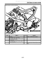
Страница 220: ...AIR INDUCTION SYSTEM 6 9 EAS27040 AIR INDUCTION SYSTEM 1 2 4 6 7 3 5 All manuals and user guides at all guides com...

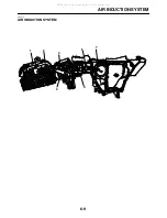
Страница 221: ...tion system hose from the air cut off valve to the cylinder head 4 Air induction system vacuum hose 5 Air cut off valve 6 Air induction system hose from the air filter to the air cut off valve 7 Air f...

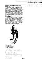
Страница 222: ...ir induction system vacuum hose 1 2 Air induction system hose from the air cut off valve to the cylinder head 1 3 Air cut off valve 1 4 Air induction system hose from the air filter to the air cut off...

Страница 223: ...cut off valve The air cut off valve is controlled by the intake gas pressure from the intake manifold Ordinari ly the air cut off valve opens to allow the air to flow during idle and closes to cut of...

Страница 224: ...AIR INDUCTION SYSTEM 6 13 All manuals and user guides at all guides com...

Страница 225: ...TEM 7 25 CIRCUIT DIAGRAM 7 25 TROUBLESHOOTING 7 27 ELECTRICAL COMPONENTS 7 29 CHECKING THE SWITCHES 7 33 CHECKING THE BULBS AND BULB SOCKETS 7 36 CHECKING THE FUSE 7 37 CHECKING AND CHARGING THE BATTE...

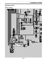
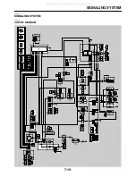
Страница 226: ...BLACK BLACK W B W B W L W R R L R L R B Br W Br W L B L B Lg Lg B W B W L W L W B B B B B B B R W R W R W B W R W L W L Y B W L Y L Y L Y L B L B R W Br R W R R R R R R R R L W L W L B L B L B Br W B...

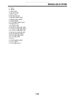
Страница 227: ...6 Battery 9 Main switch 10 Right handlebar switch 11 Engine stop switch 13 Diode 15 Sidestand switch 16 Starting circuit cut off relay 17 Diode 3 18 Neutral switch 19 C D I unit 20 Ignition coil 21 Sp...

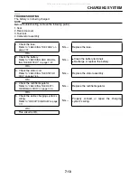
Страница 228: ...8 NG Re gap or replace the spark plug OK 4 Check the spark plug cap Refer to CHECKING THE SPARK PLUG CAP on page 7 42 NG Replace the spark plug cap OK 5 Check the ignition coil Refer to CHECKING THE I...

Страница 229: ...h OK 11 Check the clutch switch Refer to CHECKING THE SWITCHES on page 7 33 NG Replace the clutch switch OK 12 Checking the entire ignition sys tem s wiring Refer to CIRCUIT DIAGRAM on page 7 1 NG Pro...

Страница 230: ...R L R B Br G G BLACK BLACK BLACK W B W B W L W R R L R L R B Br W Br W L B L B Lg Lg B W B W L W L W B B B B B B B R W R W R W B W R W L W L Y B W L Y L Y L Y L B L B R W Br R W R R R R R R R R L W L...

Страница 231: ...otor 8 Diode 1 9 Main switch 10 Right handlebar switch 11 Engine stop switch 12 Start switch 13 Diode 2 14 Clutch switch 15 Sidestand switch 16 Starting circuit cut off relay 17 Diode 3 18 Neutral swi...

Страница 232: ...o the handlebar the clutch switch is closed and the sidestand is up the sidestand switch is closed The starting circuit cut off relay prevents the starter motor from operating when neither of these co...

Страница 233: ...CLUTCH LEVER IS PULLED TO THE HANDLEBAR 1 Battery 2 Fuse 3 Main switch 4 Diode2 5 Clutch switch 6 Sidestand switch 7 Engine stop switch 8 Neutral switch 9 Diode3 10 Starting circuit cut off relay 11...

Страница 234: ...ace the starter motor OK 4 Check the starting circuit cut off relay Refer to CHECKING THE RELAYS on page 7 40 NG Replace the starting circuit cut off relay OK 5 Check the diode2 Refer to CHECKING THE...

Страница 235: ...ge 7 33 NG Replace the sidestand switch OK 13 Check the clutch switch Refer to CHECKING THE SWITCHES on page 7 33 NG Replace the clutch switch OK 14 Check the start switch Refer to CHECKING THE SWITCH...

Страница 236: ...B B B L B Br B B B B Br BLACK BLACK W B Br W Br W L B L B Lg Lg L W L W B B B B B B B R W R W R W B W R W L W L Y L Y L B L B R W Br R W R R R R R R R R L W L W L B L B L B Br W Br W B W B W L W L W...

Страница 237: ...CHARGING SYSTEM 7 12 2 A C magneto 3 Rectifier regulator 4 Fuse 6 Battery All manuals and user guides at all guides com...

Страница 238: ...E BATTERY on page 7 37 NG Clean the battery terminals Recharge or replace the battery OK 3 Check the stator coil Refer to CHECKING THE STATOR COIL on page 7 44 NG Replace the stator assembly OK 4 Chec...

Страница 239: ...CHARGING SYSTEM 7 14 All manuals and user guides at all guides com...

Страница 240: ...Br G G BLACK BLACK BLACK W B W B W L W R R L R L R B Br W Br W L B L B Lg Lg B W B W L W L W B B B B B B B R W R W R W B W R W L W L Y B W L Y L Y L Y L B L B R W Br R W R R R R R R R R L W L W L B L...

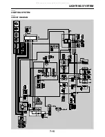
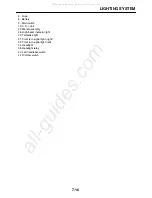
Страница 241: ...ter assembly 26 High beam indicator light 29 Tail brake light 31 Front turn signal light right 32 Front turn signal light left 34 Headlight 38 Headlight relay 40 Left handlebar switch 42 Dimmer switch...

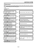
Страница 242: ...Y on page 7 37 NG Clean the battery terminals Recharge or replace the battery OK 4 Check the main switch Refer to CHECKING THE SWITCHES on page 7 33 NG Replace the main switch OK 5 Check the dimmer sw...

Страница 243: ...LIGHTING SYSTEM 7 18 All manuals and user guides at all guides com...

Страница 244: ...Br G G BLACK BLACK BLACK W B W B W L W R R L R L R B Br W Br W L B L B Lg Lg B W B W L W L W B B B B B B B R W R W R W B W R W L W L Y B W L Y L Y L Y L B L B R W Br R W R R R R R R R R L W L W L B L...

Страница 245: ...signal indicator light 28 Speed sensor 29 Tail brake light 30 Rear turn signal light right 31 Front turn signal light right 32 Front turn signal light left 33 Rear turn signal light left 35 Rear brake...

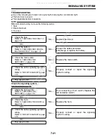
Страница 246: ...place the battery OK 3 Check the main switch Refer to CHECKING THE SWITCHES on page 7 33 NG Replace the main switch OK 4 Check the entire signaling system s wiring Refer to CIRCUIT DIAGRAM on page 7 1...

Страница 247: ...system s wiring Refer to CIRCUIT DIAGRAM on page 7 19 NG Properly connect or repair the signaling system s wiring OK This circuit is OK 1 Check the turn signal light bulb and socket Refer to CHECKING...

Страница 248: ...g Refer to CIRCUIT DIAGRAM on page 7 19 NG Properly connect or repair the signaling system s wiring OK This circuit is OK 1 Check the speed sensor Refer to CHECKING THE SPEED SENSOR on page 7 46 NG Re...

Страница 249: ...SIGNALING SYSTEM 7 24 All manuals and user guides at all guides com...

Страница 250: ...Y Y Y Br B B B B R L R B Br G G BLACK BLACK BLACK W B W B W L W R R L R B Br W Br W L B L B Lg Lg B W L W L W B B B B B B B R W R W R W B W R W L W L Y L Y L Y L Y L B L B R W Br R W R R R R R R R R L...

Страница 251: ...CARBURETOR HEATING SYSTEM 7 26 4 Fuse 6 Battery 9 Main switch 44 Thermo switch 45 Carburetor warmer All manuals and user guides at all guides com a l l g u i d e s c o m...

Страница 252: ...ean the battery terminals Recharge or replace the battery OK 3 Check the main switch Refer to CHECKING THE SWITCHES on page 7 33 NG Replace the main switch OK 4 Check the thermo switch Refer to CHECKI...

Страница 253: ...CARBURETOR HEATING SYSTEM 7 28 All manuals and user guides at all guides com...

Страница 254: ...ELECTRICAL COMPONENTS 7 29 EAS27971 ELECTRICAL COMPONENTS EAS3C51017 2 3 4 7 5 8 10 12 1 11 13 6 9 All manuals and user guides at all guides com...

Страница 255: ...Diode1 3 Diode3 4 Diode2 5 Fuse 6 Starter relay 7 Battery 8 Rectifier regulator 9 Sidestand switch 10 Rear brake light switch 11 Headlight relay 12 Starting circuit cut off relay 13 Wire harness All...

Страница 256: ...ELECTRICAL COMPONENTS 7 31 2 1 8 9 5 4 3 7 6 All manuals and user guides at all guides com a l l g u i d e s c o m...

Страница 257: ...AL COMPONENTS 7 32 1 Horn 2 CDI unit 3 Thermo switch 4 Speed sensor 5 Neutral switch 6 Carburetor warmer 7 Carburetor warmer lead 8 Ignition coil 9 Spark plug cap All manuals and user guides at all gu...

Страница 258: ...ELECTRICAL COMPONENTS 7 33 EAS27980 CHECKING THE SWITCHES 6 7 8 11 9 10 4 1 2 3 5 B B Sb Sb Sb All manuals and user guides at all guides com...

Страница 259: ...2 Dimmer switch 3 Turn signal switch 4 Clutch switch 5 Sidestand switch 6 Main switch 7 Engine stop switch 8 Start switch 9 Front brake light switch 10 Neutral switch 11 Rear brake light switch All m...

Страница 260: ...ween the switch positions a few times The terminal connections for switches e g main switch engine stop switch are shown in an illustra tion similar to the one on below The switch positions a are show...

Страница 261: ...dure applies to all of the bulbs 1 Remove Bulb WARNING EWA13320 Since the headlight bulb gets extremely hot keep flammable products and your hands away from the bulb until it has cooled down CAUTION E...

Страница 262: ...Set the main switch to OFF b Install a new fuse of the correct amperage rating c Set on the switches to verify if the electrical circuit is operational d If the fuse immediately blows again check the...

Страница 263: ...trolyte Therefore the charge of the battery has to be checked by measuring the voltage at the battery terminals 1 Remove Seat Rear right side cover Refer to GENERAL CHASSIS on page 4 1 2 Disconnect Ba...

Страница 264: ...If too high the battery will be over charged c Make sure that the current is higher than the standard charging current written on the bat tery NOTE If the current is lower than the standard charging c...

Страница 265: ...ng is incorrect re place the relay 1 Disconnect the relay from the wire harness 2 Connect the pocket tester 1 and battery 12 V to the relay terminal as shown Check the relay operation Out of specifica...

Страница 266: ...Touch probes of the pocket tester DC 20 V to the turn signal light and hazard relay cou pler as shown b Turn the main switch ON c Measure the output voltage of the turn signal light and hazard relay 1...

Страница 267: ...on Replace a Remove the spark plug cap from the spark plug lead b Connect the pocket tester 1k to the spark plug cap as shown c Measure the spark plug cap resistance Pocket tester 90890 03132 Diode2 C...

Страница 268: ...l resistance 3 Check Ignition spark gap Out of specification Follow Step 5 and later of the ignition system troubleshooting proce dure Refer to TROUBLESHOOTING on page 7 3 a Disconnect the spark plug...

Страница 269: ...l resistance EAS28150 CHECKING THE STATOR COIL 1 Disconnect Stator coil coupler from the wire harness 2 Check Stator coil resistance Out of specification Replace the pickup coil and stator assembly a...

Страница 270: ...stance Out of specification Replace a Disconnect the horn leads from the horn ter minals b Connect the pocket tester 1 to the horn terminals c Measure the horn resistance 2 Check Horn sound Faulty sou...

Страница 271: ...Out of specification Replace the thermo switch Step 1 and 2 Heating phase Step 3 and 4 Cooling phase a Connect the pocket tester 1 to the ther mo switch 1 as shown b Immerse the thermo switch in a co...

Страница 272: ...om the carburetor b Connect the pocket tester 1 to the car buretor warmer as shown c Measure the carburetor warmer resistance A When the water temperature increases B When the water temperature decrea...

Страница 273: ...EED 8 1 POOR MEDIUM AND HIGH SPEED PERFORMANCE 8 2 FAULTY GEAR SHIFTING 8 2 SHIFT PEDAL DOES NOT MOVE 8 2 JUMPS OUT OF GEAR 8 2 FAULTY CLUTCH 8 2 OVERHEATING 8 3 POOR BRAKING PERFORMANCE 8 3 FAULTY FR...

Страница 274: ...Faulty fuel pump Faulty fuel pump relay 3 Fuel cock Clogged or damaged fuel hose 4 Carburetor s Deteriorated or contaminated fuel Clogged pilot jet Clogged pilot air passage Sucked in air Damaged flo...

Страница 275: ...logged or leaking air duct Fuel system 1 Carburetor s Faulty diaphragm Incorrect fuel level Loose or clogged main jet 2 Fuel pump Faulty fuel pump EAS28530 FAULTY GEAR SHIFTING Shifting is difficult R...

Страница 276: ...ked or damaged cap bolt O ring Malfunction Bent or damaged inner tube Bent or damaged outer tube Damaged fork spring Worn or damaged outer tube bushing Bent or damaged damper rod Incorrect oil viscosi...

Страница 277: ...ake light bulb life expired Turn signal does not come on Faulty turn signal switch Faulty turn signal relay Burnt out turn signal bulb Incorrect connection Damaged or faulty wire harness Improperly gr...

Страница 278: ...ke light switch 36 Front brake light switch 37 Turn signal relay 38 Headlight relay 39 Horn 40 Left handlebar switch 41 Horn switch 42 Dimmer switch 43 Turn signal switch 44 Thermo switch 45 Carbureto...

Страница 279: ...All manuals and user guides at all guides com...

Страница 280: ...YAMAHA MOTOR CO LTD 2500 SHINGAI IWATA SHIZUOKA JAPAN PRINTED IN U S A All manuals and user guides at all guides com...

Страница 281: ...B L B Lg Lg B W B W L W L W B B B B B B B R W R W R W B W R W L W L Y B W L Y L Y L Y L B L B R W Br R W R R R R R R R R L W L W L B L B L B Br W Br W B W B W B Y B Y L L Y Y L W L W L W L W L B L B L...

Страница 282: ...K BLACK BLACK BLACK BLACK BLACK BLACK BLACK BLACK BROWN BROWN BLACK BLACK BLACK BLACK GRAY GRAY GRAY GRAY C C C B C A MAIN HARNESS MAIN HARNESS TAIL LIGHT MAIN HARNESS SPEED SENSOR CARB WARMER 2008 XT...

Отзывы: