background image

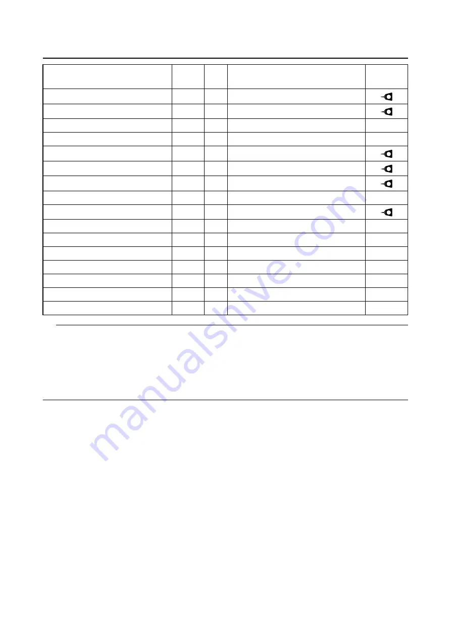
TIGHTENING TORQUES

2-11

TIP

Cylinder head bolt

First, tighten the cylinder head bolts to 40 N·m (4.0 kgf·m, 30 lb·ft) in the proper tightening sequence
and remove them. Retighten the cylinder head bolts to 23 N·m (2.3 kgf·m, 17 lb·ft) in the proper tight-
ening sequence. Tighten all bolts to reach the specified angle (90

) in a diagonal sequence, and then

tighten the cylinder head bolts further to reach the specified angle (60

) in the proper tightening se-

quence. (The first and second time, be sure to apply molybdenum disulfide grease to the bolt threads
and seats as well as to both sides of the washers.)

Shift guide bolt

M6

2

10 N·m (1.0 kgf·m, 7.4 lb·ft)

Stopper lever bolt

M6

1

10 N·m (1.0 kgf·m, 7.4 lb·ft)

Shift pedal bolt

M6

1

12 N·m (1.2 kgf·m, 8.9 lb·ft)

Generator rotor nut

M12

1

65 N·m (6.5 kgf·m, 48 lb·ft)

Stator coil screw

M5

3

10 N·m (1.0 kgf·m, 7.4 lb·ft)

Crankshaft position sensor bolt

M6

2

10 N·m (1.0 kgf·m, 7.4 lb·ft)

Stator coil assembly lead holder bolt

M5

1

8 N·m (0.8 kgf·m, 5.9 lb·ft)

Coolant temperature sensor

M10

1

15 N·m (1.5 kgf·m, 11 lb·ft)

Gear position switch bolt

M5

2

3.5 N·m (0.35 kgf·m, 2.6 lb·ft)

Rectifier/regulator bolt

M6

2

7 N·m (0.7 kgf·m, 5.2 lb·ft)

ECU bolt

M5

2

3.8 N·m (0.38 kgf·m, 2.8 lb·ft)

Ignition coil bolt

M6

2

7 N·m (0.7 kgf·m, 5.2 lb·ft)

Starter motor bolt

M6

2

10 N·m (1.0 kgf·m, 7.4 lb·ft)

Nut (holder)

M6

1

8 N·m (0.8 kgf·m, 5.9 lb·ft)

Throttle position sensor screw

M5

1

3.5 N·m (0.35 kgf·m, 2.6 lb·ft)

Intake air pressure sensor screw

M6

1

3.5 N·m (0.35 kgf·m, 2.6 lb·ft)

Item

Thread 

size

Q’ty

Tightening torques

Remarks

LT

LT

LT

LT

LT

LT

Содержание WR450F 2022

Страница 1: ...esen Sie diese Bedienungsanleitung sorgf ltig durch bevor Sie das Fahrzeug in Betrieb nehmen Leggere attentamente questo manuale prima di utilizzare questo veicolo WR450F WR450FN WR450F 2022 WR450F WR...

Страница 2: ...attentamente questo manuale prima di utilizzare questo veicolo Questo manuale dovrebbe accompagnare il veicolo se viene venduto Q Bitte lesen Sie diese Bedienungsanleitung sorgf ltig durch bevor Sie d...

Страница 3: ...Read this manual carefully before operating this vehicle 2022 OWNER S MANUAL WR450F WR450F WR450FN BDB 28199 51 E0...

Страница 4: ...Canada Ltd Canada To contact Transport Canada you may call Defect Investigations and Recall Division at 819 994 3328 or toll free 1 800 333 0510 go to www tc gc ca or email mvs sa tc gc ca or write t...

Страница 5: ...0FN OWNER S MANUAL 2022 by Yamaha Motor Co Ltd First edition July 2021 All rights reserved Any reprinting or unauthorized use without the written permission of Yamaha Motor Co Ltd is expressly prohibi...

Страница 6: ...manual is intended for those who have basic knowledge and skill concerning the servicing of Yamaha motorcycles e g Yamaha dealers service engineers etc Those who have little knowl edge and skill conce...

Страница 7: ...GENERAL INFORMATION 1 SPECIFICATIONS 2 PERIODIC CHECKS AND ADJUSTMENTS 3 CHASSIS 4 ENGINE 5 FUEL SYSTEM 6 ELECTRICAL SYSTEM 7 TROUBLESHOOTING 8 TUNING 9 EAM10003 TABLE OF CONTENTS...

Страница 8: ......

Страница 9: ...R FOR CONNECTING OPTIONAL PART For Canada 1 10 IMPORTANT INFORMATION 1 11 PREPARATION FOR REMOVAL AND DISASSEMBLY 1 11 REPLACEMENT PARTS 1 11 INSTRUMENT AND CONTROL FUNCTIONS 1 12 WARNING LIGHTS 1 12...

Страница 10: ...REAK IN PROCEDURES 1 23 SHIFTING 1 23 MAINTENANCE AFTER BREAK IN 1 25 MAJOR MAINTENANCE 1 25 AIR FILTER MAINTENANCE 1 25 TORQUE CHECK POINTS 1 26 MOTORCYCLE CARE AND STORAGE 1 28 CARE 1 28 STORAGE 1 2...

Страница 11: ...e riding 2 This motorcycle is designed to carry the oper ator only No passengers 3 The failure of motorists to detect and recog nize motorcycles in traffic is the predominat ing cause of automobile mo...

Страница 12: ...Many companies with no connection to Yamaha manufacture parts and accessories or offer oth er modifications for Yamaha vehicles Yamaha is not in a position to test the products that these aftermarket...

Страница 13: ...e fuel cock if equipped is in the OFF position and that there are no fuel leaks 3 Point the front wheel straight ahead on the trailer or in the truck bed and choke it in a rail to prevent movement 4 S...

Страница 14: ...LOCATION OF IMPORTANT LABELS 1 4 EAM20085 LOCATION OF IMPORTANT LABELS Please read the following important labels carefully before operating this vehicle CAN 7 8 13 12 1 2 3 4 5 6 9 10 11...

Страница 15: ...LOCATION OF IMPORTANT LABELS 1 5...

Страница 16: ...LOCATION OF IMPORTANT LABELS 1 6 AUS NZL ZAF EUR...

Страница 17: ...21 22 23 5 6 8 7 9 10 11 13 12 3 4 2 1 Clutch lever 2 Multi function display 3 Engine trouble warning light 4 Fuel level warning light 5 Front brake lever 6 Throttle grip 7 Start switch 8 Radiator cap...

Страница 18: ...AM30002 VEHICLE IDENTIFICATION NUMBER The vehicle identification number 1 is stamped into the right side of the frame EAM30003 ENGINE SERIAL NUMBER The engine serial number 1 is stamped into the eleva...

Страница 19: ...the engine in a closed area The exhaust gas is poisonous Never let flames near the servicing area NOTICE ECA26050 This application is designed for adjusting the settings on a standard vehicle In case...

Страница 20: ...erform the operation again 1 Turn on the smartphone 2 For two minutes after the start switch is pressed or while the engine is running the CCU is activated input the CCU serial num ber into your smart...

Страница 21: ...t to re ceive an injury or a burn on the engine the exhaust pipe the silencer or the like 6 If coolant is left adhered to the chassis paint and plating will be damaged Therefore rinse it out with wate...

Страница 22: ...circuit of the warning light can be checked by pushing the start switch The warn ing light should come on for a few seconds and then go off If the warning light does not come on initially when the sta...

Страница 23: ...e be low EAM30188 FRONT BRAKE LEVER The front brake lever 1 is located on the right handlebar Pull it toward the handlebar to acti vate the front brake EAM30189 REAR BRAKE PEDAL The rear brake pedal 1...

Страница 24: ...closing di rection the starter knob 1 moves in the direc tion b as shown and returns to its original position WARNING EWA20470 While handling the starter knob take care not to burn yourself on exhaust...

Страница 25: ...er km h Accumulated fuel consumption meter indica tor L For U K Speedometer MPH Accumulated fuel consumption meter indica tor GAL Changing the display item TIP The odometer will lock at 199999 The tri...

Страница 26: ...A button and B button simultane ously to stop the timer measurement TIP Long pushing the A button for 1 second and more while the timer measurement is being stopped will reset the value 3 Push the A b...

Страница 27: ...ven if the set tings are not finished and the setting mode dis play will disappear The display has been turned off The vehicle has been moved A communication error has occurred Setting the backlight b...

Страница 28: ...Push the B button to change the units of the speedometer and fuel The unit display will change in the following order Except for U K Accumulated fuel consumption meter L GAL L Speedometer km h MPH km...

Страница 29: ...s set as 100 Pushing the B button at a setting value of 110 will return the setting to 90 2 Push the A button to set the fuel consumption correction value The correction value will then be kept and th...

Страница 30: ...the setting mode A button Odometer ODO TRIP A TRIP B Clock Timer Accumulated fuel consumption Setting the timer Putting measurement on standby A button B button Auto start Manual start A button Measu...

Страница 31: ...2 ODO 3 TRIP A 4 TRIP B 5 Clock 6 Timer 7 Accumulated fuel consumption 8 SETTING MODE 9 Setting the backlight brightness 10 Setting the clock time hour 11 Setting the clock time minute 12 Setting the...

Страница 32: ...ar ea The exhaust fumes are poisonous they can cause loss of consciousness and death in a very short time Always operate the ma chine in a well ventilated area NOTICE ECA25910 If the throttle is open...

Страница 33: ...left idling for 7 minutes If the engine stops push the start switch to restart the engine 2 Make a pit stop and check mounted areas for looseness oil leaks or other problems 3 Then drive it for about...

Страница 34: ...ch lever in 5 Shift the transmission into second gear Make sure not to shift the transmission into the neutral position 6 Open the throttle part way and gradually re lease the clutch lever 7 Follow th...

Страница 35: ...and nuts Check for looseness in mounted areas of parts as well as engine mounting bolts and engine brackets 2 For the chassis Check welds and mounted areas of the frame the swingarm the link the brac...

Страница 36: ...frame Link to rear shock absorber Link to swingarm Mounting of rear shock absorber Rear shock absorber and frame Mounting of swingarm Tightening of pivot shaft Wheel s Mounting of wheel Front Tighten...

Страница 37: ...t pedal Shift pedal to shift shaft Plastic cover Tightening of front fender Tightening of fork leg protector Tightening of air scoop Left cover to rear frame Tightening of side cover Tightening of rea...

Страница 38: ...y rinse the area off with water immediately dry it and then apply a corrosion protec tion spray Improper cleaning can damage plastic parts such as cowlings panels wind shields headlight lenses meter l...

Страница 39: ...nd nickel plated sur faces 5 Use spray oil as a universal cleaner to re move any remaining dirt 6 Touch up minor paint damage caused by stones etc 7 Wax all painted surfaces 8 Let the motorcycle dry c...

Страница 40: ...rk plug and then install the spark plug and the spark plug cap WARNING To pre vent damage or injury from sparking make sure to ground the spark plug electrodes while turning the engine over 4 Lubricat...

Страница 41: ...NERAL SPECIFICATIONS 2 1 ENGINE SPECIFICATIONS 2 2 CHASSIS SPECIFICATIONS 2 4 ELECTRICAL SPECIFICATIONS 2 7 TIGHTENING TORQUES 2 8 GENERAL TIGHTENING TORQUE SPECIFICATIONS 2 8 ENGINE TIGHTENING TORQUE...

Страница 42: ...6 in Overall width 825 mm 32 5 in Overall height 1270 mm 50 0 in Seat height 955 mm 37 6 in Wheelbase 1480 mm 58 3 in Ground clearance 320 mm 12 60 in Weight Curb weight 119 kg 262 lb Shift up points...

Страница 43: ...3 L 0 67 US qt 0 55 Imp qt With oil filter removal 0 65 L 0 69 US qt 0 57 Imp qt Quantity disassembled 0 90 L 0 95 US qt 0 79 Imp qt Cooling system Coolant quantity Radiator including all routes 1 03...

Страница 44: ...25 Secondary reduction ratio 3 846 50 13 Final drive Chain Air filter Air filter element Wet element Air filter oil grade Yamaha foam air filter oil or other quality foam air filter oil Idling condit...

Страница 45: ...CAN Rear tire Type With tube Size 120 90 18 65M CAN 140 80 18 70R AUS AUT BEL CHE CYP CZE DEU DNK ESP FIN FRA GBR GRC HRV HUN IRL ITA NLD NOR NZL POL PRT SVK SVN SWE TUR ZAF Manufacturer model DUNLOP...

Страница 46: ...e from the start position Soft 20 Adjustment value from the start position STD 12 Adjustment value from the start position Hard 0 Rear suspension Type Swingarm link suspension Spring Coil spring Shock...

Страница 47: ...nt Click Adjustment value from the start position Soft 20 Adjustment value from the start position STD 10 Adjustment value from the start position Hard 0 Drive chain Size 520 Chain type Sealed type Nu...

Страница 48: ...y 12 V 6 0 Ah 10 HR Headlight Bulb type Halogen bulb Bulb wattage Headlight HS1 35 0 W 35 0 W Brake tail light LED Meter lighting EL Electroluminescent Indicator light Fuel level warning light LED Eng...

Страница 49: ...o avoid warpage tight en multi fastener assemblies in a crisscross pat tern and progressive stages until the specified tightening torque is reached Unless otherwise specified tightening torque specifi...

Страница 50: ...ut M14 1 50 N m 5 0 kgf m 37 lb ft Use a lock washer Balancer nut M10 1 45 N m 4 5 kgf m 33 lb ft Use a lock washer Timing chain guide stopper plate exhaust side M6 1 10 N m 1 0 kgf m 7 4 lb ft Timing...

Страница 51: ...cessing screw M36 1 10 N m 1 0 kgf m 7 4 lb ft Timing mark accessing screw M14 1 6 N m 0 6 kgf m 4 4 lb ft Drive sprocket cover bolt M6 2 7 N m 0 7 kgf m 5 2 lb ft Crankcase bearing cover plate screw...

Страница 52: ...N m 1 0 kgf m 7 4 lb ft Shift pedal bolt M6 1 12 N m 1 2 kgf m 8 9 lb ft Generator rotor nut M12 1 65 N m 6 5 kgf m 48 lb ft Stator coil screw M5 3 10 N m 1 0 kgf m 7 4 lb ft Crankshaft position senso...

Страница 53: ...p switch screw M3 1 0 5 N m 0 05 kgf m 0 37 lb ft Start switch M3 1 0 5 N m 0 05 kgf m 0 37 lb ft Mode switch Except for Canada M3 1 1 3 N m 0 13 kgf m 0 95 lb ft Lower ring nut M28 1 See TIP Damper a...

Страница 54: ...l axle pinch bolt M8 4 21 N m 2 1 kgf m 15 lb ft Front brake disc bolt M6 6 12 N m 1 2 kgf m 8 9 lb ft Rear brake disc bolt M6 6 12 N m 1 2 kgf m 8 9 lb ft Footrest bracket bolt M10 4 55 N m 5 5 kgf m...

Страница 55: ...35 kgf m 2 6 lb ft Drive chain tensioner bolt upper side M8 1 16 N m 1 6 kgf m 12 lb ft Drive chain tensioner bolt lower side M8 1 16 N m 1 6 kgf m 12 lb ft Bolt drive chain support M6 1 7 N m 0 7 kgf...

Страница 56: ...2 16 N m 1 6 kgf m 12 lb ft Headlight body and headlight stay bolt M6 2 7 N m 0 7 kgf m 5 2 lb ft Multi function meter screw M5 2 1 3 N m 0 13 kgf m 0 95 lb ft Multi function meter bracket bolt M6 1...

Страница 57: ...THE CYLINDER HEAD BREATHER HOSE 3 15 CHECKING THE EXHAUST SYSTEM 3 15 CHECKING THE COOLANT LEVEL 3 16 CHECKING THE COOLING SYSTEM 3 17 CHANGING THE COOLANT 3 17 CHASSIS 3 19 ADJUSTING THE FRONT DISC...

Страница 58: ...NG AND LUBRICATING THE CABLES 3 29 LUBRICATING THE BRAKE LEVER 3 30 LUBRICATING THE CLUTCH LEVER 3 30 LUBRICATING THE PEDAL 3 30 CHECKING THE SIDESTAND 3 30 LUBRICATING THE SIDESTAND 3 30 ELECTRICAL S...

Страница 59: ...Odometer readings 600 mi 1000 km or 1 month 1800 mi 3000 km or 3 months 3000 mi 5000 km or 6 months 1 Fuel line Check fuel hoses for cracks or damage Replace if necessary 2 Spark plug Check condition...

Страница 60: ...chain slack alignment and condition Adjust and lubricate chain with a special O ring chain lubricant thoroughly Every ride 12 Steering bearings Check bearing assemblies for looseness Moderately repack...

Страница 61: ...ce to the list below Items marked with an asterisk should be performed by a Yamaha dealer as they require special tools data and technical skills No Item Routine After break in Every race Every third...

Страница 62: ...nt Every two years Inspect hoses 22 Outside nuts and bolts Retighten 23 Air filter Clean and lubricate Replace 24 Oil filter Replace 25 Engine guard Replace 26 Frame Clean and inspect 27 Fuel tank fue...

Страница 63: ...hten 37 Relay arm connect ing rod Inspect lube and retighten 38 Sidestand Lubricate 39 Steering head Inspect free play and retighten Clean and lubricate Replace bearings 40 Tire wheels Inspect air pre...

Страница 64: ...ar brake 3 19 3 19 3 19 3 20 3 20 3 20 3 20 3 21 Drive chain Check drive chain slack and alignment Check that the drive chain is lubricated properly 3 22 4 32 4 32 4 33 4 33 4 33 Wheels Check for exce...

Страница 65: ...ter TDC 1 Remove Seat Side cover left right Air scoop left right Fuel tank Refer to FUEL TANK on page 6 1 ECU Engine Control Unit 2 Remove Spark plug Cylinder head cover 3 Remove Timing mark accessing...

Страница 66: ...3 Install Digital tachometer TIP Get the high tension cord 1 of the ignition coil pinched in the detector a of the digital tachom eter 4 Measure Engine idling speed Out of specification Regulate 5 Adj...

Страница 67: ...force to pull the hose TIP Remove the fuel tank turn this 180 clockwise and put it in the frame 2 as shown 2 Remove Spark plug cap Spark plug NOTICE ECA24410 In order not to allow the dirt accumulate...

Страница 68: ...l check bolt Drain it until its last drop is out NOTICE ECA24290 Since engine oil also lubricates the clutch the wrong oil types or additives could cause clutch slippage Therefore do not add any chemi...

Страница 69: ...Install Oil filler cap 9 Check Oil level Refer to CHECKING THE ENGINE OIL LEVEL on page 3 10 10 Check Engine oil pressure a Start the engine WARNING EWA19130 Always keep the engine idling speed durin...

Страница 70: ...annot be obtained on the handlebar side use the adjuster on the clutch cable side Clutch cable side a Slide the clutch cable cover b Loosen the locknut 1 c Turn the adjuster 2 until the specified clut...

Страница 71: ...rub it thoroughly so that the element is evenly permeated with the oil c Wrap the element in a clean cloth rub the element gently and wipe off any excess oil TIP The element should be permeated with...

Страница 72: ...the two ribs c locat ed on the left and right sides of the air filter case cover with the projections d on the air scoop and then install the air filter case cover 10 Install Fuel tank cap cover EAM3...

Страница 73: ...ust pipe and muffler are cool before cleaning the spark arrester Do not start the engine when cleaning the exhaust system 1 Remove Exhaust pipe 1 Exhaust pipe 2 Refer to EXHAUST SYSTEM on page 5 1 2 R...

Страница 74: ...radiator cap when the en gine is hot Scalding hot fluid and steam may be blown out which could cause serious in jury When the engine has cooled open the radiator cap as follows Place a thick rag or a...

Страница 75: ...at Side cover left right Refer to GENERAL CHASSIS on page 4 1 EAM30212 CHANGING THE COOLANT WARNING EWA13030 A hot radiator is under pressure Therefore do not remove the radiator cap when the en gine...

Страница 76: ...ra tion of the coolant Use only distilled water However if dis tilled water is not available soft water may be used If coolant comes into contact with painted surfaces immediately wash them with wa te...

Страница 77: ...TING THE REAR DISC BRAKE 1 Adjust Brake pedal position a Loosen the locknut 1 b Turn the adjusting bolt 2 until the brake pedal is in the correct position c Tighten the locknut WARNING EWA19150 A soft...

Страница 78: ...the brake pads 1 Operate the brake 2 Check Front brake pad Wear indicator grooves 1 almost touch the brake disc Replace the brake pads as a set Refer to FRONT BRAKE on page 4 7 EAM30232 CHECKING THE R...

Страница 79: ...ficult it may be necessary to let the brake fluid settle for a few hours Repeat the bleeding procedure when the tiny bubbles in the hose have disappeared 2 Bleed the brake system a Fill the reservoir...

Страница 80: ...ack WARNING EWA13120 Securely support the vehicle so that there is no danger of it falling over 1 Adjust Drive chain slack a Loosen the wheel axle nut 1 b Loosen both locknuts 2 c Turn the adjusting b...

Страница 81: ...gle to the steering nut wrench Move the steering to the left and right a couple of times to check that it moves smoothly c Turn the front fork to the right and left a few times and make sure that the...

Страница 82: ...he handlebar several times and check if the front fork rebounds smoothly Unsmooth operation Correct or replace Refer to FRONT FORK on page 4 16 TIP If any damage is found or the front fork does not op...

Страница 83: ...1 Adjust Compression damping a Turn the adjuster 1 in the direction of a or b to make an adjustment TIP Although the total number of clicks of a damping force adjusting mechanism may not exactly matc...

Страница 84: ...orber assembly smooth ac tion Rear suspension link smooth action Sit astride the seat and shake your body up and down several times to check whether the rear shock absorber assembly operates smoothly...

Страница 85: ...necessary Compression damping for fast compres sion damping NOTICE ECA24370 Do not turn the adjuster forcibly beyond its adjusting range 1 Adjust Compression damping for fast compression damping a Tur...

Страница 86: ...ould be advisable to check the number of clicks of each damping force adjusting mechanism and to modify the specifications as necessary EAM30240 CHECKING THE SWINGARM OPERATION 1 Check Swingarm smooth...

Страница 87: ...reak in is done until the initial looseness in nipples disap pears Make sure that tightening is done in stages not at a time EAM30245 CHECKING THE WHEELS 1 Check Wheel Damage out of round Replace WARN...

Страница 88: ...ting points and metal to metal moving parts of the following parts Clutch lever EAM30250 LUBRICATING THE PEDAL 1 Lubricate the pivoting point and metal to met al moving parts of the pedal EAM30504 CHE...

Страница 89: ...the headlight unit bolts lift and remove the headlight unit 2 Remove Headlight coupler 1 Bulb cover 2 3 Remove Headlight bulb 1 4 Install Headlight bulb Fasten the new headlight bulb with the head lig...

Страница 90: ...ELECTRICAL SYSTEM 3 32...

Страница 91: ...4 9 REPLACING THE REAR BRAKE PADS 4 9 HANDLEBAR 4 11 REMOVING THE HANDLEBAR 4 11 CHECKING THE HANDLEBAR 4 11 INSTALLING THE HANDLEBAR 4 11 FRONT FORK 4 16 REMOVING THE FRONT FORK LEGS 4 16 DISASSEMBLI...

Страница 92: ...CHAIN DRIVE 4 32 REMOVING THE DRIVE CHAIN 4 32 CHECKING THE DRIVE CHAIN 4 32 CHECKING THE DRIVE SPROCKET 4 33 CHECKING THE REAR WHEEL SPROCKET 4 33 INSTALLING THE DRIVE CHAIN 4 33...

Страница 93: ...ilter case in serting the grooves c into the ribs d of the air filter case and inserting the projection e into the slot f in the air filter case install the air scoop and secure it with the bolts EAM3...

Страница 94: ...GENERAL CHASSIS 4 2 a Projection b Slot c Rib side cover d Rib rear fender a a a 1 1 c c b b d d...

Страница 95: ...he brake disc 1 between the brake pads 2 correctly 2 Install Front wheel sensor Front wheel sensor bracket NOTICE ECA21020 Make sure there are no foreign materials in the front wheel sensor rotor and...

Страница 96: ...by an impact during ser vice and caught foreign materials If there is any defective part repair or replace the de fective part TIP Measure the distance between the front wheel sensor rotor and front w...

Страница 97: ...1 4 tooth wear a Replace the rear wheel sprocket and the drive sprocket as a set Bent tooth Replace the rear wheel sprock et and the drive sprocket as a set 2 Replace Rear wheel sprocket a Remove the...

Страница 98: ...ear wheel axle 4 Install Drive chain puller right 1 Washer 2 Rear wheel axle nut 3 TIP Temporarily tighten the rear wheel axle nut at this point 5 Adjust Drive chain slack a Refer to DRIVE CHAIN SLACK...

Страница 99: ...specification Replace the brake pads as a set 3 Install Brake pad a Connect the plastic hose 1 to the bleed screw 2 and place a container under the end of the plastic hose b Loosen the bleed screw and...

Страница 100: ...fer to CHECKING THE BRAKE FLUID LEVEL on page 3 19 5 Check Brake lever operation A softy or spongy feeling Bleed the brake system Refer to BLEEDING THE HYDRAULIC BRAKE SYSTEM on page 3 21 Bolt brake c...

Страница 101: ...of specification Replace the brake pads as a set 3 Install Brake pad a Connect the plastic hose 1 to the bleed screw 2 and place a container under the end of the plastic hose b Loosen the bleed screw...

Страница 102: ...fluid level Refer to CHECKING THE BRAKE FLUID LEVEL on page 3 19 5 Check Brake pedal operation A softy or spongy feeling Bleed the brake system Refer to BLEEDING THE HYDRAULIC BRAKE SYSTEM on page 3 2...

Страница 103: ...aken it EAM30054 INSTALLING THE HANDLEBAR 1 Stand the vehicle upright on a level surface WARNING EWA13120 Securely support the vehicle so that there is no danger of it falling over 2 Install Damper 1...

Страница 104: ...en Lower handlebar holder nut 4 Install Clutch lever holder 1 Clutch lever 2 TIP The clutch lever holder 1 should be installed according to the dimensions shown 5 Install Engine stop switch 1 Mode swi...

Страница 105: ...7 Install Clutch cable 1 TIP Before installation apply the lithium soap based grease to the clutch cable end 8 Adjust Clutch lever free play Refer to ADJUSTING THE CLUTCH LEVER FREE PLAY on page 3 12...

Страница 106: ...le grip 3 moves smoothly If it does not retighten the screws for adjustment 13 Install Rubber cover 1 Cover throttle cable housing 2 14 Install Start switch 1 Front brake master cylinder assembly 2 Fr...

Страница 107: ...HANDLEBAR 4 15 15 Adjust Throttle grip free play Refer to CHECKING THE THROTTLE GRIP on page 3 8 Throttle grip free play 3 0 6 0 mm 0 12 0 24 in 2 5 1 4 3 4...

Страница 108: ...emove Front fork leg EAM30056 DISASSEMBLING THE FRONT FORK LEGS 1 Drain Fork oil 2 Remove Adjuster 1 from the inner tube TIP While compressing the inner tube 2 set the cap bolt ring wrench 4 between t...

Страница 109: ...erously weaken it 2 Check Outer tube Scratches wear damage Replace 3 Measure Fork spring free length a Out of specification Replace 4 Check Damper assembly 1 Bend damage Replace O ring 2 Wear damage R...

Страница 110: ...er tube bushing Slide metal Oil seal Copper washer Before assembling the front fork leg make sure that all of the components are clean 1 Stretch the damper assembly fully 2 Fill Damper assembly NOTICE...

Страница 111: ...ion Unless the damping force adjuster is fully loos ened correct damping characteristic cannot be obtained after installation 7 Install Base valve 1 to the damper assembly 2 TIP First bring the damper...

Страница 112: ...e damper assem bly 12 Allow the overflowing oil to escape at the hole a in the damper assembly TIP The overflow measures about 10 cm 0 34 US oz 0 35 Imp oz 13 Check Damper assembly smooth movement Tig...

Страница 113: ...ct the oil seal lip 15 Install Piston metal 1 TIP Install the piston metal onto the slot on inner tube 16 Install Outer tube 1 to the inner tube 2 17 Install Slide metal 1 Washer 2 to the outer tube T...

Страница 114: ...t the steps 14 to 20 22 Measure Distance a Out of specification Turn the locknut to specification 23 Install Upper spring seat 1 Fork spring 2 to the damper assembly 3 TIP Install the upper spring sea...

Страница 115: ...the damper assembly 4 TIP While compressing the inner tube 5 set the cap bolt ring wrench 7 between the inner tube and locknut 6 Fully finger tighten the adjuster onto the damp er assembly 27 Measure...

Страница 116: ...ghten the damper assembly 32 Install Protector guide 1 EAM30059 INSTALLING THE FRONT FORK LEGS 1 Install Front fork 1 TIP Temporarily tighten the lower bracket pinch bolts Do not tighten the upper bra...

Страница 117: ...fork protector 6 Install Protector 1 Bolt protector 2 7 Adjust Rebound damping force TIP Turn in the damping adjuster 1 finger tight and then turn out to the originally set position Cap bolt ring wre...

Страница 118: ...FRONT FORK 4 26 8 Adjust Compression damping force TIP Turn in the damping adjuster 1 finger tight and then turn out to the originally set position 1 1...

Страница 119: ...itting Replace 3 Replace Bearing Bearing race a Remove the bearing race from the steer ing head pipe with a long rod 1 and a hammer b Remove the bearing race from the lower bracket with a chisel 2 and...

Страница 120: ...teering ring nut with its stepped side a facing downward Tighten the steering ring nut with a steering nut wrench 2 Refer to CHECKING AND ADJUSTING THE STEERING HEAD on page 3 23 5 Check the steering...

Страница 121: ...teering ring nut little by lit tle 10 Adjust Front fork top end a 11 Tighten Upper bracket pinch bolt 1 Lower bracket pinch bolt 2 WARNING EWA19330 Tighten the lower bracket to specified torque If tor...

Страница 122: ...1 TIP While removing the rear shock absorber assem bly lower bolt hold the swingarm so that it does not drop down 3 Remove Rear shock absorber assembly upper bolt Rear shock absorber assembly EAM30067...

Страница 123: ...al movement a Measure the tightening torque of the pivot shaft nut b Check the swingarm side play a by mov ing the swingarm from side to side If the swingarm has side to side play check the bushings t...

Страница 124: ...ner sides length b between pin outer sides 2 TIP When measuring a 15 link section of the drive chain make sure that the drive chain is taut Perform this procedure 2 3 times at a different location eac...

Страница 125: ...OCKET Refer to CHECKING AND REPLACING THE REAR WHEEL SPROCKET on page 4 5 EAM30079 INSTALLING THE DRIVE CHAIN 1 Install Drive chain NOTICE ECA17410 Be sure to put on safety goggles when work ing TIP I...

Страница 126: ...dramatically shorten the drive chain s life 4 Adjust Drive chain slack Refer to DRIVE CHAIN SLACK on page 3 22 NOTICE ECA24590 A drive chain that is too tight will overload the engine and other vital...

Страница 127: ...E FRICTION PLATES 5 2 CHECKING THE CLUTCH PLATES 5 2 CHECKING THE CLUTCH SPRINGS 5 2 CHECKING THE CLUTCH HOUSING 5 2 CHECKING THE CLUTCH BOSS 5 3 CHECKING THE PRESSURE PLATE 5 3 CHECKING THE PUSH LEVE...

Страница 128: ...ction a on the exhaust pipe 4 or silencer 5 Be sure to insert the projection b into the slot in the exhaust pipe or silencer 3 Install Clamp Silencer 1 Bolt silencer 2 4 Tighten Bolt exhaust pipe 2 Cl...

Страница 129: ...lace the clutch plates as a set EAM30111 CHECKING THE CLUTCH SPRINGS 1 Check Clutch spring Damage Replace the clutch springs as a set 2 Measure Clutch spring free length Out of specification Replace t...

Страница 130: ...wear Replace the primary drive and primary driven gears as a set Excessive noise during operation Replace the primary drive and primary driven gears as a set 2 Check Primary drive gear to primary driv...

Страница 131: ...gns with the balancer end slot 4 Tighten the crankcase cover bolts right in stages and in a crisscross pattern 4 Install Push lever shaft 1 TIP Apply the lithium soap based grease on the oil seal lip...

Страница 132: ...d friction plates alter nately on the clutch boss starting with a friction plate and ending with a friction plate From the clutch boss side install the friction plates in order friction plate 1 identi...

Страница 133: ...spring bolt TIP Tighten the bolts in stages and in a crisscross pattern 13 Install O ring 1 TIP Apply the lithium soap based grease to the O ring 14 Install Clutch cover Clutch cover bolt TIP Tighten...

Страница 134: ...CLUTCH 5 7...

Страница 135: ...1 2 3 4 5 6 7 8 9 10 FUEL SYSTEM FUEL TANK 6 1 REMOVING THE FUEL TANK 6 1 INSTALLING THE FUEL TANK 6 1...

Страница 136: ...the two buttons 2 on the sides of the connector and then remove the hose Before removing the hose place a few cloths in the area under where it will be removed To prevent sand dust and other foreign m...

Страница 137: ...FUEL TANK 6 2 3 Connect Fuel pump coupler 4 Install Air scoop left right Seat Side cover left right Refer to GENERAL CHASSIS on page 4 1 1 a...

Страница 138: ...FUEL TANK 6 3...

Страница 139: ...7 8 9 10 ELECTRICAL SYSTEM FUEL INJECTION SYSTEM 7 1 ECU SELF DIAGNOSTIC FUNCTION 7 1 ELECTRICAL COMPONENTS 7 3 CHECKING THE BULBS AND BULB SOCKETS 7 3 CHECKING THE FUSES 7 3 CHECKING AND CHARGING THE...

Страница 140: ...gine trouble warning light Engine trouble warning light indication and fuel injection system operation The engine trouble warning light flashes when any one of the following conditions is present and...

Страница 141: ...g light and provides the engine with alternate operating instructions that are appropriate for the type of malfunction When an abnormal signal is received from a sensor the ECU processes the specified...

Страница 142: ...all of the fus es 1 Remove Seat Refer to GENERAL CHASSIS on page 4 1 2 Check Main fuse 1 Radiator fan motor fuse 2 a Connect the digital circuit tester to the fuse and check the continuity TIP Set th...

Страница 143: ...Lead Acid battery are different from those of conventional batteries The VRLA Valve Regulated Lead Acid battery should be charged according to the appropriate charging method If the battery is over c...

Страница 144: ...comes hot to the touch at any time during the charging process dis connect the battery charger and let the bat tery cool before reconnecting it Hot batteries can explode As shown in the following illu...

Страница 145: ...ure that the current is higher than the standard charging current written on the battery TIP If the current is lower than the standard charging current written on the battery this type of battery char...

Страница 146: ...ELECTRICAL COMPONENTS 7 7...

Страница 147: ...SSION 8 6 TROUBLESHOOTING OF COOLING SYSTEM 8 7 TROUBLESHOOTING OF BRAKE 8 8 TROUBLESHOOTING OF SUSPENSION 8 8 TROUBLESHOOTING OF STEERING HANDLING 8 10 TROUBLESHOOTING OF CHARGING SYSTEM 8 11 TROUBLE...

Страница 148: ...ngine will not start or is difficult to start but it cranks Symptom Possible cause Actions Starter motor does not operate Have a Yamaha dealer check the electrical system Starter motor operates but th...

Страница 149: ...g Replace the piston and piston rings as a set Seized or damaged piston Replace the piston and piston rings as a set Worn or damaged cylinder bore Replace the cylinder piston and piston rings as a set...

Страница 150: ...ecified torque Clogged air filter element Clean or replace the air filter ele ment Incorrect oil level high Adjust the oil level to the specified level Symptom Possible cause Actions Noise heard from...

Страница 151: ...ve gear Replace the balancer drive gear and balancer shaft as a set Worn or damaged big end bearing Replace the big end bearing Worn or damaged crankshaft jour nal bearing Replace the crankshaft journ...

Страница 152: ...bushing Replace the clutch housing Improperly installed pull lever Align the match mark on the pull lever before installation Incorrect oil level Adjust the engine oil level to the specified level Inc...

Страница 153: ...ransmis sion gears Remove foreign object from trans mission gears Seized transmission gear Replace the seized gear and the axle as a set Improperly assembled transmis sion Reassemble the transmission...

Страница 154: ...radiator Faulty radiator fan motor Have a Yamaha dealer check the electrical system Damaged or faulty water pump Replace the water pump Damaged hoses or pipes Replace the hose or pipe Improperly conne...

Страница 155: ...Damaged brake hose and brake pipe Replace the brake hose and brake pipe Oil or grease on the brake disc or brake pad Clean the brake disc or brake pad Insufficient lubrication of brake lever or brake...

Страница 156: ...er rod assembly bolt Tighten the damper rod assembly bolt to the specified torque Damaged damper rod assembly bolt copper washer Replace the damper rod assembly bolt copper washer Cracked or damaged c...

Страница 157: ...ed torque Worn bearing or bearing race Replace the bearing and bearing race as a set Warped front fork Repair or replace the front fork Bent front wheel axle Replace the front wheel axle Incorrect tir...

Страница 158: ...lace the swingarm bearing Damaged or worn swingarm bear ing or bushing Replace the swingarm bearing or bushing Symptom Possible cause Actions Battery is not charged Have a Yamaha dealer check the elec...

Страница 159: ...or stuck throttle position sensor is detected 21 Coolant temperature sensor open or short circuit detected 22 Intake air temperature sensor open or short circuit detected 30 The vehicle has overturned...

Страница 160: ...SELF DIAGNOSTIC FUNCTION AND DIAGNOSTIC CODE TABLE 8 13...

Страница 161: ...E 9 1 FRONT FORK SETTING 9 1 CHANGE IN AMOUNT AND CHARACTERISTICS OF FORK OIL 9 2 SETTING OF SPRING AFTER REPLACEMENT 9 2 FRONT FORK SETTING PARTS 9 3 REAR SUSPENSION SETTING 9 3 CHOOSING SET LENGTH 9...

Страница 162: ...line with care taken to avoid the en gine over revving TIP Riding technique varies from rider to rider and the performance of a machine also vary from machine to machine Therefore do not imitate other...

Страница 163: ...ten dency to be stiffer with the consequent dete riorated performance and characteristics Therefore adjust the front fork within the specified range EAM30173 SETTING OF SPRING AFTER REPLACEMENT As the...

Страница 164: ...he rear fender holding bolt 2 Remove the stand or block from the engine and with a rider astride the seat measure the sunken length b between the rear wheel axle center and the rear fender holding bol...

Страница 165: ...force WARNING EWA19200 When using a rear shock absorber other than currently installed use the one whose overall length a does not exceed the stan dard as it may result in faulty performance Never use...

Страница 166: ...ER AS SEMBLY on page 3 26 Spring preload adjusting positions Minimum Position in which the spring is turned in 1 5 mm 0 06 in from its free length Standard Position in which the spring is turned in 10...

Страница 167: ...ticeable scars etc If any replace affected parts Slide metal Replace with a new one for extended use Piston metal Replace with a new one for extended use Lower bracket tightening torque Retighten to s...

Страница 168: ...unt Increase oil amount by about 5 cm 0 2 US oz 0 2 Imp oz Obtrusive front tending to upper front posture Compression damping force Turn adjuster counterclockwise about 2 clicks to decrease damping Ba...

Страница 169: ...enger is astride seat Spring Replace with soft spring Bottoming out High compres sion damping Turn adjuster clockwise about 1 6 turn to increase damping Spring set length Set sunken length for 90 100...

Страница 170: ...CHASSIS 9 9...

Страница 171: ...sure sensor 32 Speed sensor 33 Engine stop switch 34 Gear position switch 35 Mode switch Except for Cana da 36 Diode 1 37 Starting circuit cut off relay 38 Clutch switch 39 Start switch 40 Diode 4 41...

Страница 172: ...PRINTED IN JAPAN E...

Страница 173: ...attentamente questo manuale prima di utilizzare questo veicolo Questo manuale dovrebbe accompagnare il veicolo se viene venduto Q Bitte lesen Sie diese Bedienungsanleitung sorgf ltig durch bevor Sie d...

Страница 174: ...esen Sie diese Bedienungsanleitung sorgf ltig durch bevor Sie das Fahrzeug in Betrieb nehmen Leggere attentamente questo manuale prima di utilizzare questo veicolo WR450F WR450FN WR450F 2022 WR450F WR...

Страница 175: ...R W Br R W Br R L R L R L R L B L B L B L B L B L B L B L B L B L B L B L R L B L B L B B B L L B B R L Br B L B L W L B B B B Br W L L L L L L L L L R L R L R L R L R L B L B L B L B L B L B L B L L...

Страница 176: ...B PUSH FREE ON OFF ON OFF B B WR450F WR450FN 2022 WIRING DIAGRAM WR450F WR450FN 2022 SCH MA DE C BLAGE WR450F WR450FN 2022 SCHALTPLAN WR450F WR450FN 2022 SCHEMA ELETTRICO WR450F WR450FN 2022 DIAGRAMA...

Отзывы: