–5–
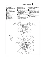
1
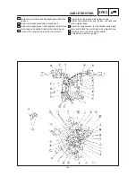
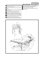
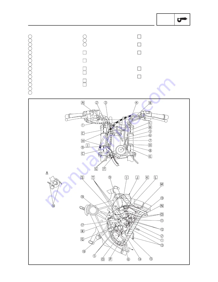
Throttle cable 1
2
Right handlebar switch lead
3
Brake hose
4
Clutch cable
5
Main switch lead
6
Left handlebar switch lead
7
Horn lead
8
Starter cable
9
Speed sensor lead
10
Coolant reservoir hose
11
Headlight lead
12
Meter light lead
13
Thermo unit lead
14
Thermo switch lead
15
Fan motor lead
CABLE ROUTING
SPEC
16
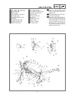
Ignition coil (left) lead
17
Ignition coil (right) lead
18
Negative lead
A Fasten the right handlebar switch
lead with a plastic band.
B Fasten the handlebar switch lead
with a plastic band.
C 50 mm
D Fasten the horn lead with a plastic
band.
E 60 mm
F Set the clamp within 10 mm from
the upper end of protector.
G Align the brake hose white mark to
the mark of bracket.
H Fasten the brake hose with a plas-
tic band and cut the end of band.
I Pass the speed sensor lead be-
tween throttle cable and clutch
cable and fasten to the frame head
pipe.
J Pass the wireharness and hoses
under the frame.
K Fasten the coolant reservoir hose
with a plastic band.
CABLE ROUTING
Содержание TDM850 1999
Страница 1: ......
Страница 31: ... 25 SIGNAL SYSTEM ELEC EB806000 SIGNAL SYSTEM CIRCUIT DIAGRAM ...


