Instrument an
d
control functions
4-10
4
EAU14883
A
d
justin
g
the shock a
b
sor
b
er
assem
b
lies
WARNING
EWA10211
Always a
d
just
b
oth shock a
b
sor
b
er
assem
b
lies equally, otherwise poor
han
d
lin
g
an
d
loss of sta
b
ility may re-
sult.
Each shock absorber assembly is
equipped with a spring preload adjust-
ing ring.
NOTICE
ECA10102
To avoi
d
d
ama
g
in
g
the mechanism,
d
o not attempt to turn
b
eyon
d
the
maximum or minimum settin
g
s.
Adjust the spring preload as follows.
To increase the spring preload and
thereby harden the suspension, turn
the adjusting ring on each shock ab-
sorber assembly in direction (a). To de-
crease the spring preload and thereby
soften the suspension, turn the adjust-
ing ring on each shock absorber as-
sembly in direction (b).
Align the appropriate notch in the ad-
justing ring with the position indicator
on the shock absorber.
EAU15306
Si
d
estan
d
The sidestand is located on the left
side of the frame. Raise the sidestand
or lower it with your foot while holding
the vehicle upright.
TIP
The built-in sidestand switch is part of
the ignition circuit cut-off system,
which cuts the ignition in certain situa-
tions. (See the following section for an
explanation of the ignition circuit cut-
off system.)
WARNING
EWA10242
The vehicle must not
b
e ri
dd
en with
the si
d
estan
d
d
own, or if the si
d
e-
stan
d
cannot
b
e properly move
d
up
(or
d
oes not stay up), otherwise the
si
d
estan
d
coul
d
contact the
g
roun
d
an
d
d
istract the operator, resultin
g
in a possi
b
le loss of control.
Yamaha’s i
g
nition circuit cut-off
system has
b
een
d
esi
g
ne
d
to assist
the operator in fulfillin
g
the respon-
si
b
ility of raisin
g
the si
d
estan
d
b
e-
fore startin
g
off. Therefore, check
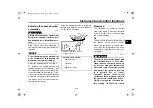
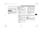
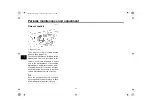
1. Spring preload adjusting ring
2. Position indicator
Sprin
g
preloa
d
settin
g
:
Minimum (soft):
1
Standard:
2
Maximum (hard):
5
U1BE26E0.book Page 10 Thursday, June 25, 2015 9:38 AM


