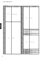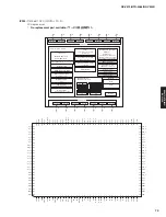
Pin
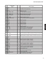
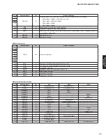
No.
Port Name
Function Name
(P.C.B.)
I/O
Detail of Function
FULL ON
PPWER OFF
MCU sleep
A
C
OFF
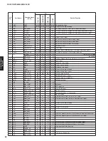
53
P5_4
HP_N_DET
I+
O
O
O
Headphone detection / L: Headphone detected
54
P13_3
HPRY
O
O
O
O
Headphone relay control
55
P13_2
SPRY_SB_BA
O
O
O
O
Speaker relay control (Surround back and Bi-Amp)
56
P13_1
(no use)
57
P13_0
SPRY_5CH
O
O
O
O
Speaker relay control (Front / Center / Surround) / H: Relay ON
58
P5_3
MT_N_SB
O
O
O
O
Mute control (Surround back)
59
P5_2
(no use)
O
O
O
O
60
P5_1
MT_N_5CH
O
O
O
O
Mute control (Front / Center / Surround)
61
P5_0
E8A_N_CE
I+
I+
I+
I+
62
P12_7
OSDFS_N_CS
O
O
O
O
Chip select control of OSD Flash from microprocessor
63
P12_6
USB_VBUS_PON
O
O
O
O
64
P12_5
PRY
O
O
O
O
Power relay control / H: On
65
TXD7
FPGA_MOSI
SO
SO
O
SO
FPGA, OSD Flash synchronization data output
66
RXD7
FPGA_MISO
SI
SI
O
O
FPGA, OSD Flash synchronization data input
67
CLK7
FPGA_SCK
SO
SO
O
SO
FPGA, OSD Flash synchronous clock output
68
P4_4
REM_OUT
O
O
O
O
Remote control code (spare)
69
P4_3
(no use)
I+
I+
I+
I+
70
P4_2
(no use)
I+
I+
I+
I+
71
P4_1
N_FCT
I
I
I
I
FCT detection / H: Product mode, L: FCT mode
72
P4_0
NDAC_N_MT
O
O
O
O
Mute control
73
P3_7
O
O
O
O
L: ROHM/FPGA SPI / H: Spalta OSD SPI
74
P3_6
VOL_RB
I+
I+
I+
I+
Volume rotary encoder B
75
P3_5
VOL_RA
I+
I+
I+
I+
Volume rotary encoder A
76
P3_4
FLD_N_CS
O
O
O
O
FL driver chip select
77
P3_3
FLD_N_RST
O
O
O
O
FL driver reset
78
P3_2
MIC_N_DET
I-
I-
I-
I-
MIC detection / L: MIC detected
79
P3_1
STBY_LED
O
O
O
O
Standby through LED / H: LED lighting
80
P12_4
NCPU_PON
O
O
O
O
H: Power supply ON
81
P12_3
DSP_PON
O
H: Power supply ON
82
P12_2
+3.3S_PON
O
H: Power supply ON
83
P12_1
HDMI_PON
O
H: Power supply ON
84
P12_0
VID_PON
O
H: Power supply ON
85
VCC2
VCC2
MCU
MCU
MCU
MCU
Microprocessor power supply
86
P3_0
EEP_N_CS
O
O
O
O
EEPROM chip select
87
VSS
VSS
MCU
MCU
MCU
MCU
Microprocessor ground
88
P2_7
MODE
I+
I+
I+
I+
+3.3V: Normal movement / 0V: MAC address writing permission
89
P2_6
(reserved)
90
N_INT7
REM_IN
IRQ
IRQ
IRQ
I
Remote control pulse input
91
N_INT6
PSW_N_DET
IRQ
IRQ
IRQ
I
Power system switch (Power, Scene) detection / L: Standby key ON
92
P2_3
DSP_N_RST
O
O
O
O
DSP reset
93
P2_2
DSP_N_RDY
I+
I+
O
I+
DSP Ready input
94
P2_1
DSP_N_CS
O
O
O
O
DSP chip select
95
P2_0
DSP_FMT
O
O
O
O
DSP full mute output / H: Mute
96
P1_7
PWM_PDN
O
O
O
O
Digital amplifier power down control
(reserved)
97
P1_6
NCPU_VBUSDRV
I-
I-
I-
I-
USB power supply output requirement from NETWORK microprocessor
98
N_INT3
MHL_WAKE
(reserved)
99
P1_4
PWM_N_RST
O
O
O
O
Digital amplifier reset
(reserved)
100
TXD6
NCPU_SPI_MOSI
SO
O
O
O
NET SPI data output
101
RXD6
NCPU_SPI_MISO
SI
O
O
O
NET SPI data input
102
CLK6
NCPU_SPI_SCK
NET SPI clock output
103
P1_0
NCPU_SPI_N_CS
O
O
O
O
NET SPI chip select
81
RX-V475/HTR-4066/RX-V500D
RX-V475/HTR-4066/
RX-V50
0D
Содержание RX-V500D
Страница 9: ...RX V500D A model RX V500D B G models 9 RX V475 HTR 4066 RX V500D RX V475 HTR 4066 RX V500D ...
Страница 132: ... CONFIGURING THE SYSTEM SETTINGS RX V475 HTR 4066 RX V500D 133 ...
Страница 133: ... システム設定を変更する RX V475 HTR 4066 RX V500D 134 ...
Страница 146: ...147 RX V475 HTR 4066 RX V500D RX V475 HTR 4066 RX V500D MEMO ...
Страница 147: ...RX V475 HTR 4066 RX V500D ...


