PSR-9000
13
16
Keyboard Assembly
16-1 Remove the lower case. (See procedure 1.)
16-2 Remove the DP circuit board. (See procedure 14.)
16-3 Remove the DM circuit board and TG circuit board.
(See procedure 15.)
16-4 Remove the AM circuit board. (See procedure 2.)
16-5 Remove the five (5) screws marked [40e]. The DM
circuit board holder can then be removed. (Fig. 7)
17
MK Circuit Board
17-1 Remove the lower case. (See procedure 1.)
17-2 Remove the DP circuit board. (See procedure 14.)
17-3 Remove the DM circuit board and TG circuit board.
(See procedure 15.)
17-4 Remove the AM circuit board. (See procedure 2.)
17-5 Remove the AM shield cover. (See procedure 16.)
17-6 Remove the eighteen (18) screws marked [5]. The
MK circuit board can then be removed. (Fig. 8)
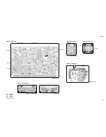
(Fig. 8)
[5]: Bind Head Tapping Screw-S 3.0X10 MFZN2Y (EP630630)
[50d] x 3
[40g] x 2
[40e] x 5
[40g] x 2
[40f] x 3
(Fig. 7)
[40]: Bind Head Tapping Screw-B 3.0X8 MFZN2Y (EP600250)
[50]: Bind Head Tapping Screw-B 3.0X6 MFZN2Y (EP600130)
Upper case
Keyboard assembly
16-6 Remove the three (3) screws marked [40f]. The AM
shield cover can then be removed. (Fig. 7)
16-7 Remove the three (3) screws marked [50d] and the
four (4) screws marked [40g]. The keyboard assembly
can then be removed. (Fig. 7)
MK
[5] x 18


