■
DISASSEMBLY PROCEDURES
(分解手順)
Fig. 1
(図 1)
1. Upper
Case
Assembly
(Time required: About 2 minutes)
1-1
Remove the eleven (11) screws marked [60] and the
three (3) screws marked [80]. The upper case assembly
can then be removed. (Fig. 1)
Disassembly procedures of the MX61 and MX49 are almost
the same.
For that reason, we explain disassembly procedure of the
MX61 as a representative here.
1.
上ケース Ass'y
(所要時間:約 2 分)
1-1 [60]のネジ 11 本と[80]のネジ 3 本を外し、上ケー
ス Ass'y を外します。(図 1)
MX61 と MX49 の分解手順はほぼ同じです。そのため、こ
こでは代表として MX61 の分解手順を説明します。
Caution:
Be sure to attach the removed filament tape just
as it was before removal.
注意:
分解時に取り外したフィラメントテープは、必ず元
通りに取り付けてください。
Lower key bed assembly
(下ケース鍵盤 Ass'y)
Upper case assembly
(上ケース Ass'y)
[80]
[60]
[60]
[60]
<Bottom view
(底面図)
>
8
MX61/MX49
Содержание MX61
Страница 15: ...R8A02042BG YC479A00 SWX08 DM IC101 15 MX61 MX49...
Страница 16: ...16 MX61 MX49...
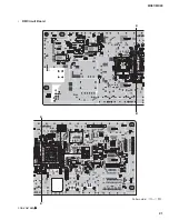
Страница 21: ...B B B B DM Circuit Board 2NA ZA67560 1 Pattern side 21 MX61 MX49...
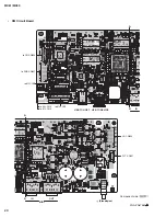
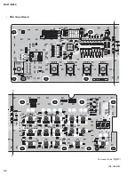
Страница 26: ...to DM CN402 to 61H CN3 F F F F 49L Circuit Board MX49 only Component side 2NA ZA13490 26 MX61 MX49...
Страница 27: ...G G G G 49L Circuit Board MX49 only 2NA ZA13490 Pattern side 27 MX61 MX49...
Страница 53: ...6 USB 7 7 1 38 7 2 ENTER 1 001 Version 7 3 ENTER 7 4 Factory Set ENTER 038 Factory Set 4 X XX 5 53 MX61 MX49...


