


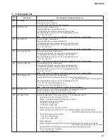


4. Other
Inspections
Turn on the [ ] (STANDBY/ON) switch to start up on the normal mode.
Pop-Noise (PHONES)
Connect the oscilloscope to the [PHONES] terminal (L and R).
Turn on and off the [ ] (STANDBY/ON) switch sequentially.
Confi rm each output level is as follows at that time.
PHONES L: 500mVp-p or less
PHONES R: 500mVp-p or less
Pop-Noise (OUTPUT)
Connect the oscilloscope to the OUTPUT terminals ([L/MONO] and [R]).
Insert the jacks to both the [L/MONO] and [R] terminals at the same time.
Turn on and off the [ ] (STANDBY/ON) switch sequentially.
Confi rm each output level is as follows at that time.
OUTPUT L: 500mVp-p or less
OUTPUT R: 500mVp-p or less
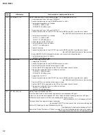
Noise Level (PHONES)
Connect the level meter to the [PHONES] terminal (L and R).
Confi rm each output level is as follows at that time.
PHONES L: -85.0dBu or less
PHONES R: -85.0dBu or less
Noise Level (OUTPUT)
Connect the level meter to the OUTPUT terminals ([L/MONO] and [R]).
Insert the jacks to both the [L/MONO] and [R] terminals at the same time.
Confi rm each output level is as follows at that time.
OUTPUT L: -85.0dBu or less
OUTPUT R: -85.0dBu or less
AUX IN
Connect the level meter to the OUTPUT terminals ([L/MONO] and [R]).
Insert the jacks to both the [L/MONO] and [R] terminals at the same time.
Connect the oscillator to the INPUT terminals ([L] and [R]), and input the 1kHz ±5Hz, -6.0dBu sine wave.
Confi rm each output level is as follows at that time.
OUTPUT L: +1.4dBu ±2dB
OUTPUT R: +1.4dBu ±2dB
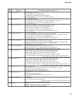
5. Initial
Settings
Set each controller to the factory default settings as follows.
[ ] (STANDBY/ON) switch : OFF
[MASTER VOLUME]
: Min.
[DAW LEVEL]
: Min.
A/D INPUT [GAIN]
: Min.
MODULATION WHEEL
: Min.
36
MX61/MX49
Содержание MX61
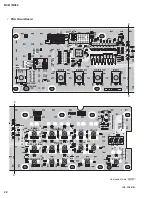
Страница 15: ...R8A02042BG YC479A00 SWX08 DM IC101 15 MX61 MX49...
Страница 16: ...16 MX61 MX49...
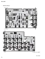
Страница 21: ...B B B B DM Circuit Board 2NA ZA67560 1 Pattern side 21 MX61 MX49...
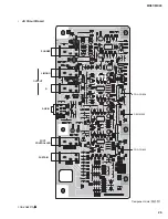
Страница 26: ...to DM CN402 to 61H CN3 F F F F 49L Circuit Board MX49 only Component side 2NA ZA13490 26 MX61 MX49...
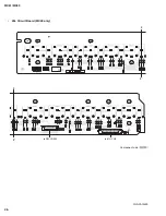
Страница 27: ...G G G G 49L Circuit Board MX49 only 2NA ZA13490 Pattern side 27 MX61 MX49...
Страница 53: ...6 USB 7 7 1 38 7 2 ENTER 1 001 Version 7 3 ENTER 7 4 Factory Set ENTER 038 Factory Set 4 X XX 5 53 MX61 MX49...


