INSTALLING THE INCLUDED PARTS
– 6 –
7
9
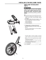
3. Installing the handlebar
Install the handlebar
a
so that the knurled part
b
is at the center of the handlebar holder
c
,
then tighten the 4 handlebar holder
c
bolts
d
to the specified torque.
TIP
Install the handlebar
a
so that the brake levers
e
are at a 30
angle to the handlebar, as shown in the
illustration.
TIP
8
Tighten bolts
d
evenly in stages, in the order
shown in the illustration.
8
Tighten in such a way that the gaps
f
above
and below the handlebar holder
c
are equal.
4. Installing the headlight
Install the headlight
a
to the bracket
b
as
shown, then tighten the bolt
c
to the specified
torque.
TIP
Install in such a way that the headlight points down-
ward from horizontal and shines on the road
approximately 33 feet (10 meters) ahead.
a
b
d
d
c
Tightening torque 6 N·m (0.6 kgf·m, 4.4 lb·ft)
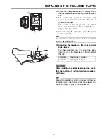
The handlebar
a
should not touch the frame
when it is turned fully to the left or right.
NOTICE
a
e
3
0°
d
c
f
f
a
b
c
Tightening torque 7 N·m (0.7 kgf·m, 5.2 lb·ft)
Содержание CROSS CORE 2018
Страница 1: ...2018 ASSEMBLY MANUAL CROSS CORE PW70CRL PW70CRM PW70CRS LIT 15666 00 03 X1M 28107 12 ...
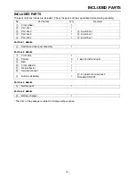
Страница 5: ...INCLUDED PARTS 3 7 9 1 2 0 q w 6 7 8 9 3 4 5 r t e ...
Страница 17: ......
Страница 18: ......


