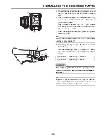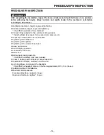
INSTALLING THE INCLUDED PARTS
– 8 –
7
9
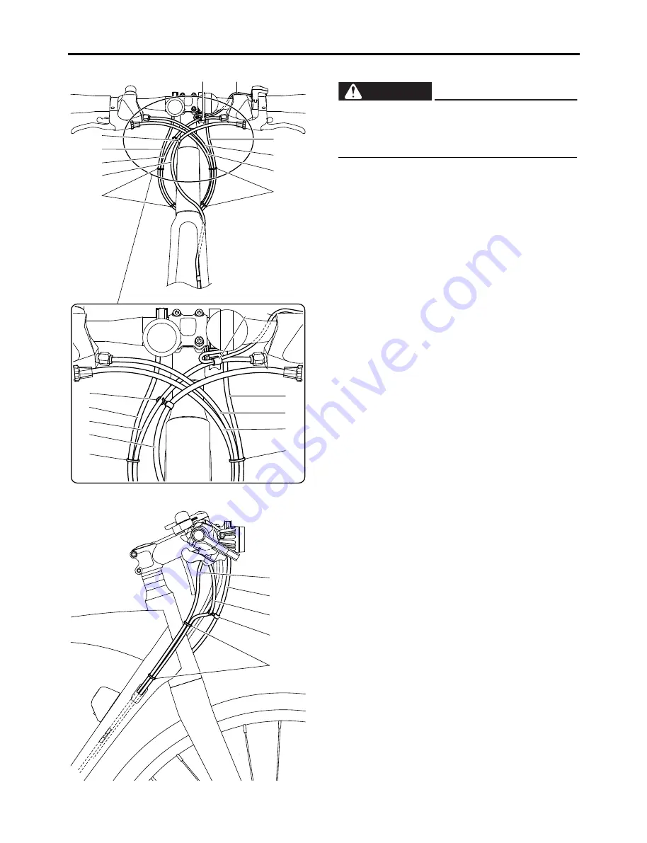
7. Routing the wires
Confirm that wires are routed in order starting
from front to back
Front brake wire
1
Rear brake wire
2
Rear shift wire
3
Front shift wire
4
Headlight lead
5
Switch unit lead
6
Display unit lead
7
Clamp the front brake wire
1
and front shift
wire
4
with the wire clip
8
at the position
shown in the illustration.
Clamp the front shift wire
4
, and headlight lead
5
with the plastic locking ties
9
at the position
shown in the illustration.
Clamp the rear brake wire
2
, rear shift wire
3
and display unit lead
7
with the plastic locking
ties
0
at the position shown in the illustration.
Clamp the front shift wire
4
and switch unit lead
6
with the wire clip
q
at the position shown in
the illustration.
Check that the front brake wire
1
, front shift
wire
4
, headlight lead
5
, wire clip
8
, and plas-
tic locking ties
9
are placed as shown in the
illustration.
9
4
1
5
8
0
2
3
7
q
6
9
4
1
5
8
0
2
3
7
q 6
Be sure to route the wires as shown in the illus-
tration. If not, they could interfere with handle-
bar operation which could cause loss of
control.
WARNING
5
1
4
8
9
Содержание CROSS CORE 2018
Страница 1: ...2018 ASSEMBLY MANUAL CROSS CORE PW70CRL PW70CRM PW70CRS LIT 15666 00 03 X1M 28107 12 ...
Страница 5: ...INCLUDED PARTS 3 7 9 1 2 0 q w 6 7 8 9 3 4 5 r t e ...
Страница 17: ......
Страница 18: ......


