CL3/CL1
147
2. Tests not requiring PC application
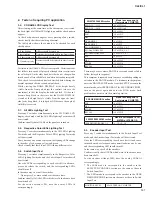
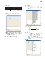
2-0. CN NAME LCD Display Test
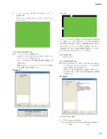
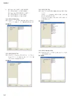
After starting, at the same time as the check mode is activated,
the back light of all Mini LCDs lights up and the check pattern
appears.
As the check pattern changes at every pressing of any switch,
check visually that there is nothing abnormal.
The table below shows the contents to be checked for each
check pattern.
All dot lighting
All dots should be turned on.
Frame lighting
Outermost dots should light in the frame shape.
All dots turned off
All dots should be turned off.
CH number display
Numbers should be displayed in order from the
left.
Variation in the NAME LCD test is acceptable. Variation means
that all dots turn on and off properly although there is variation in
the color depth. On the other hand, dots that do not change when
turned on and off are called black dots/white dots and unacceptable.
Also, check for reversed contrast as described below during the
normal operation check or sound output check.
While viewing the NAME DISPLAY at the height barely
visible from the front pad, adjust the contrast (close to the
maximum) so that the display looks deep black. If it doesn’t
become deep black in that state but the NAME DISPLAY
viewed at the height barely visible from the opposite (rear)
side looks deep black, it is judged as NG because the angle of
visibility is reversed.
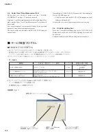
2-1. All LEDs Lighting Test
Press any 3 switches simultaneously in the CH NAME LCD
display check mode, and the All LEDs Lighting Test mode will
be activated.
Con
fi
rm visually that all LEDs on the panel are turned on.
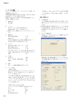
2-2. Respective Color LEDs Lighting Test
Press any 3 switches simultaneously in the All LEDs Lighting
Test mode, and the Respective Color LEDs Lighting Test mode
will be activated.
Every time any one switch is pressed, the lighting LEDs change
in the order of red, orange, yellow and green.
Check visually that there is no LED lit in any different color.
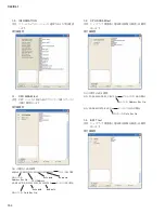
2-3. Switch Input Test
Press any 3 switches simultaneously in the Respective Color
LEDs Lighting Test mode, and the Switch Input Test mode will
be activated.
Have the LEDs corresponding to each switch lit in advance,
press and release the switch, and the corresponding LEDs
should turn off.
In the same way, check all the switches.
* Do not press 2 or more switches at the same time.
Con
fi
rm visually if all the LEDs which were lit in advance have
been turned off.
For the switch without LED, have the nearby LEDs lit
correspondingly.
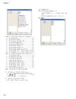
SELECTED CHANNEL section
Made to correspond to
Centaralogic CH METER
SEND 1,3,...,13,15
-60 of CH1 to 8
SEND 2,4,...,14,16
-30 of CH1 to 8
GAIN
-18 of CH1
PAN
-18 of CH2
HPF
-12 of CH3
DYNAMICS 1
-6 of CH1
DYNAMICS 2
-6 of CH2
EQ–Q H,HM,LM,L
-18 of CH4, 5, 6, 7
EQ–Freq H,HM,LM,L
-12 of CH4, 5, 6, 7
EQ–GAIN H,HM,LM,L
-6 of CH4, 5, 6, 7
INC
-6 of CH8
DEC
-18 of CH3
STORE
-12 of CH8
RECALL
-18 of CH8
There may be cases where DANTE is reset and switches fail to
follow (delayed in response).
This symptom is repeated every ten some seconds depending on
variation in the DANTE module. To eliminate such symptom,
enter the DANTE SETUP mode from the SETUP screen in the
normal mode, select REDUNDANT for SECONDARY PORT,
turn on the power again and enter the DIAG mode. Such
problem does not occur in the normal operation.
SCENE MEMORY section
Made to correspond to
Centaralogic CH METER
INC
-6 of CH8
DEC
-18 of CH3
STORE
-12 of CH8
RECALL
-18 of CH8
USER DEFINED KNOBS section
Made to correspond to CH
METER of STEREO A
USER DEFINED KNOBS 1 – 4
–6,–12,–18,–30
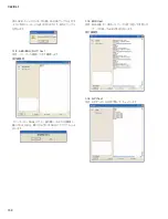
2-4. Encoder Input Test
Press any 3 switches simultaneously in the Switch Input Test
mode, and the Encoder Input Test mode will be activated.
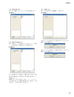
Have the LEDs corresponding to each encoder lit in advance,
turn each encoder clockwise and counterclockwise one by one,
and the corresponding LED should turn off.
In the same way, check all the encoders.
Con
fi
rm visually that all LEDs which were lit in advance have
been turned off.
For the encoder without LED, have the nearby LEDs lit
correspondingly.
* The LEDs made to correspond to the encoder in the
SELECTED CHANNEL section are the same as those in
Switch Input Test.
* The LEDs made to correspond to the encoder in the USER
DEFINED KNOBS section are the same as those in Switch
Input Test.
MONITOR LEVEL
-60 of STEREO A CH METER
Содержание CL3
Страница 7: ...7 CL3 CL1 DIMENSIONS CL3 CL1 648 15 201 130 299 667 839 15 201 130 299 667 Unit mm...
Страница 95: ...95 CL3 CL1 CPU Circuit Board Pattern side to DSP CN101 2NA WY67750 1...
Страница 100: ...CL3 CL1 100 DNTU Circuit Board Component side to DSP CN552 to DANTE MODULE 64CH to DSP CN553 Scale 80 100 2NA WZ20390 5...
Страница 101: ...101 CL3 CL1 DNTU Circuit Board Pattern side Scale 80 100 2NA WZ20390 5...
Страница 102: ...CL3 CL1 102 2NA WY63530 FX Circuit Board WR 63 1 Component side Scale 95 100...
Страница 103: ...103 CL3 CL1 2NA WY63530 FX Circuit Board Pattern side Scale 95 100...
Страница 104: ...CL3 CL1 104 HAAD Circuit Board Component side Scale 90 100 to DSP CN871 to DCMS CN734 2NA WY64340 2...
Страница 105: ...105 CL3 CL1 HAAD Circuit Board Pattern side Scale 90 100 2NA WY64340 2...
Страница 106: ...CL3 CL1 106 Component side DA Circuit Board 1 1 WR 63 1 WR 06 1 WR 63 1 Scale 85 100 2NA WY64350 2...
Страница 107: ...107 CL3 CL1 2NA WY63490 Component side JK Circuit Board WR 63 1...
Страница 109: ...109 CL3 CL1 Component side TBPHN Circuit Board WR 06 1 WR 63 1 2NA WY64360 1...
Страница 110: ...CL3 CL1 110 Component side PN8 Circuit Board to FD8 CN902 or FD8CN CN902 2NA WY53120 2...
Страница 114: ...CL3 CL1 114 PNM Circuit Board Component side Scale 90 100 WR 31 15 1 WR 31 1 C C C C 2NA WY63300 1...
Страница 116: ...CL3 CL1 116 PN2 Circuit Board Component side Pattern side WR 310 1 WR 31 1 WR 1 0 2NA WY63300 1...
Страница 118: ...CL3 CL1 118 Component side PNENL Circuit Board to PN8 CN001 2NA WY53130 1...
Страница 158: ...CL3 CL1 158 UNLOCK WORD CLOCK BNC 1 12 AES EBU OUT test 1KHz OK NG 1 13 MIDI test MIDI 1 14 GPI Test OUT IN...
Страница 160: ...CL3 CL1 160 1 18 LCD Test LCD LCD 1 3 2 9 5 OK NG 1 2 H 3 O X O 4 BOX 5x4...
Страница 178: ...CL3 CL1 178 Status Updating 1 1 6 OK Status Update Done 7 DANTE CONTROLLER Device Status Status Error CL...
Страница 382: ...7 MBCL CIRCUIT BOARDS A A A A 2NA WY53200 1 MB Circuit Board Component side...
Страница 383: ...MBCL 8 MB Circuit Board DSUB PH CONNECTOR ASSEMBLY B B B B 2NA WY53200 1 Pattern side...


