


EPS (ELECTRIC POWER STEERING) SYSTEM (for EPS models)
9-72
After the mode selection judgment is completed (present display or past malfunction mode), the current
fault code signaling stops immediately, and then the EPS warning light starts flashing at 1.5-second in-
tervals.
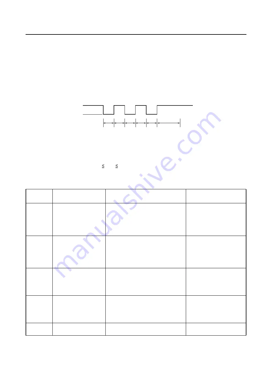
Deleting fault codes
To delete fault codes, ground the EPS self-diagnosis signal connector 3 or more times within 5 seconds
while the present or past malfunction mode is activated. The currently selected mode remains active
after the fault codes of that mode are deleted.
T1: Connector grounded - - - - 0.1
T1
1.6 seconds
T2: Fault codes deleted - - - - - Maximum 1.5 seconds required
EBS30290
SELF-DIAGNOSTIC FUNCTION TABLE (EPS SYSTEM)
a
b
c
T1
T1
T1
T1
T1
T2
a. EPS self-diagnosis signal connector
b. Disconnected
c. Grounded
Fault code
No.
Item
Symptom
Probable cause of mal-
function
11
13
15
16
EPS torque sensor
No normal signals are received from
the torque sensor.
• Open or short circuit in
wire harness.
• Malfunction in torque sen-
sor.
• Malfunction in EPS control
unit.
21
Speed sensor
No normal signals are received from
the speed sensor.
• Open or short circuit in
wire harness.
• Malfunction in speed sen-
sor.
• Malfunction in EPS control
unit.
22
Engine speed signal
No normal signals are received from
the ECU.
• Open or short circuit in
wire harness.
• Malfunction in ECU.
• Malfunction in EPS control
unit.
41
42
43
45
EPS motor
No normal signals are received from
the EPS motor.
• Open or short circuit in
wire harness.
• Malfunction in EPS motor.
• Malfunction in EPS control
unit.
52
EPS control unit
Relay contacts in the EPS control unit
are welded together.
Malfunction in EPS control
unit.
Содержание 2016 Grizzly yf700gg
Страница 6: ......
Страница 8: ......
Страница 11: ...IDENTIFICATION 1 2 ...
Страница 37: ...ENGINE SPECIFICATIONS 2 6 Air induction system Solenoid resistance 18 22 Ω ...
Страница 58: ...LUBRICATION SYSTEM CHART AND DIAGRAMS 2 27 EBS30023 LUBRICATION DIAGRAMS 6 7 8 9 3 4 3 2 1 5 ...
Страница 60: ...LUBRICATION SYSTEM CHART AND DIAGRAMS 2 29 1 2 3 4 5 ...
Страница 62: ...COOLING SYSTEM DIAGRAMS 2 31 EBS20021 COOLING SYSTEM DIAGRAMS 1 2 3 10 9 8 6 7 5 4 ...
Страница 72: ...CABLE ROUTING 2 41 Engine right side view 2 C E 1 9 10 E 1 9 10 E 5 6 9 A B C D 1 2 3 4 5 6 7 8 ...
Страница 76: ...CABLE ROUTING 2 45 Engine top view B 5 6 7 8 9 10 11 12 13 14 15 16 17 A 1 2 3 4 19 20 21 22 C 18 11 17 17 ...
Страница 78: ...CABLE ROUTING 2 47 Front and rear brake hoses F 3 F 3 F 3 3 I G H 4 4 B C D 2 E D 2 A 1 ...
Страница 80: ...CABLE ROUTING 2 49 ...
Страница 83: ......
Страница 119: ...PERIODIC MAINTENANCE 3 36 A Headlight left and right B Handle mounted light b a 1 A b a 1 B ...
Страница 120: ...PERIODIC MAINTENANCE 3 37 ...
Страница 183: ...STEERING STEM 4 60 TIP Align the punch mark a on the EPS unit with the groove b in the pitman arm 1 b a ...
Страница 197: ...REAR ARMS AND REAR SHOCK ABSORBER ASSEMBLIES 4 74 7 9 8 9 7 3 5 4 5 3 6 2 10 10 1 ...
Страница 198: ...REAR ARMS AND REAR SHOCK ABSORBER ASSEMBLIES 4 75 ...
Страница 203: ...ENGINE INSPECTION 5 2 Top cover Refer to GENERAL CHASSIS 2 on page 4 6 ...
Страница 244: ...ELECTRIC STARTER 5 43 a b b 1 2 3 ...
Страница 316: ...AIR INDUCTION SYSTEM 7 9 EBS20057 AIR INDUCTION SYSTEM 3 4 1 2 3 4 1 2 ...
Страница 352: ...REAR CONSTANT VELOCITY SHAFT ASSEMBLIES FINAL DRIVE ASSEMBLY AND REAR DRIVE SHAFT 8 31 ...
Страница 355: ......
Страница 365: ...ELECTRIC STARTING SYSTEM 9 10 ...
Страница 369: ...CHARGING SYSTEM 9 14 ...
Страница 417: ...FUEL PUMP SYSTEM 9 62 ...
Страница 432: ...ELECTRICAL COMPONENTS 9 77 EBS20084 ELECTRICAL COMPONENTS 4 5 6 7 8 9 10 11 12 13 14 15 16 17 19 18 1 2 3 ...
Страница 434: ...ELECTRICAL COMPONENTS 9 79 1 2 3 5 7 8 9 10 11 12 13 14 15 16 17 18 19 4 6 ...
Страница 454: ...ELECTRICAL COMPONENTS 9 99 ...
Страница 461: ...TROUBLESHOOTING 10 6 Too many electrical accessories Incorrect connection Faulty tail brake light assembly ...
Страница 468: ......
Страница 469: ......
Страница 470: ......