


FUEL INJECTION SYSTEM
9-31
EBS30278
ECU SELF-DIAGNOSTIC FUNCTION
The ECU is equipped with a self-diagnostic function in order to ensure that the fuel injection system is
operating normally. If this function detects a malfunction in the system, it immediately operates the en-
gine under substitute characteristics and illuminates the engine trouble warning light to alert the rider
that a malfunction has occurred in the system. Once a malfunction has been detected, a fault code is
stored in the memory of the ECU.
• To inform the rider that the fuel injection system is not functioning, the engine trouble warning light
comes on or flashes when the start switch is being pushed to start the engine.
• If a malfunction is detected in the system by the self-diagnostic function, the ECU provides an appro-
priate substitute characteristic operation, and alerts the rider of the detected malfunction by illuminat-
ing the engine trouble warning light.
• After the engine has been stopped, the lowest fault code number appears on the multi-function meter
display. Once a fault code has been displayed, it remains stored in the memory of the ECU until it is
deleted.
Engine trouble warning light indication and fuel injection system operation
* The warning light flashes when any one of the conditions listed below is present and the start switch
“
” is pushed:
Checking for a defective engine trouble warning light bulb
The engine trouble warning light comes on for around 2 seconds after the main switch has been turned
to “
” (on). If the warning light does not come on under these conditions, the warning light (LED) may
be defective.
ECU detects an abnormal signal from a sensor
If the ECU detects an abnormal signal from a sensor while the vehicle is being driven, the ECU illumi-
nates the engine trouble warning light and provides the engine with alternate operating instructions that
are appropriate for the type of malfunction.
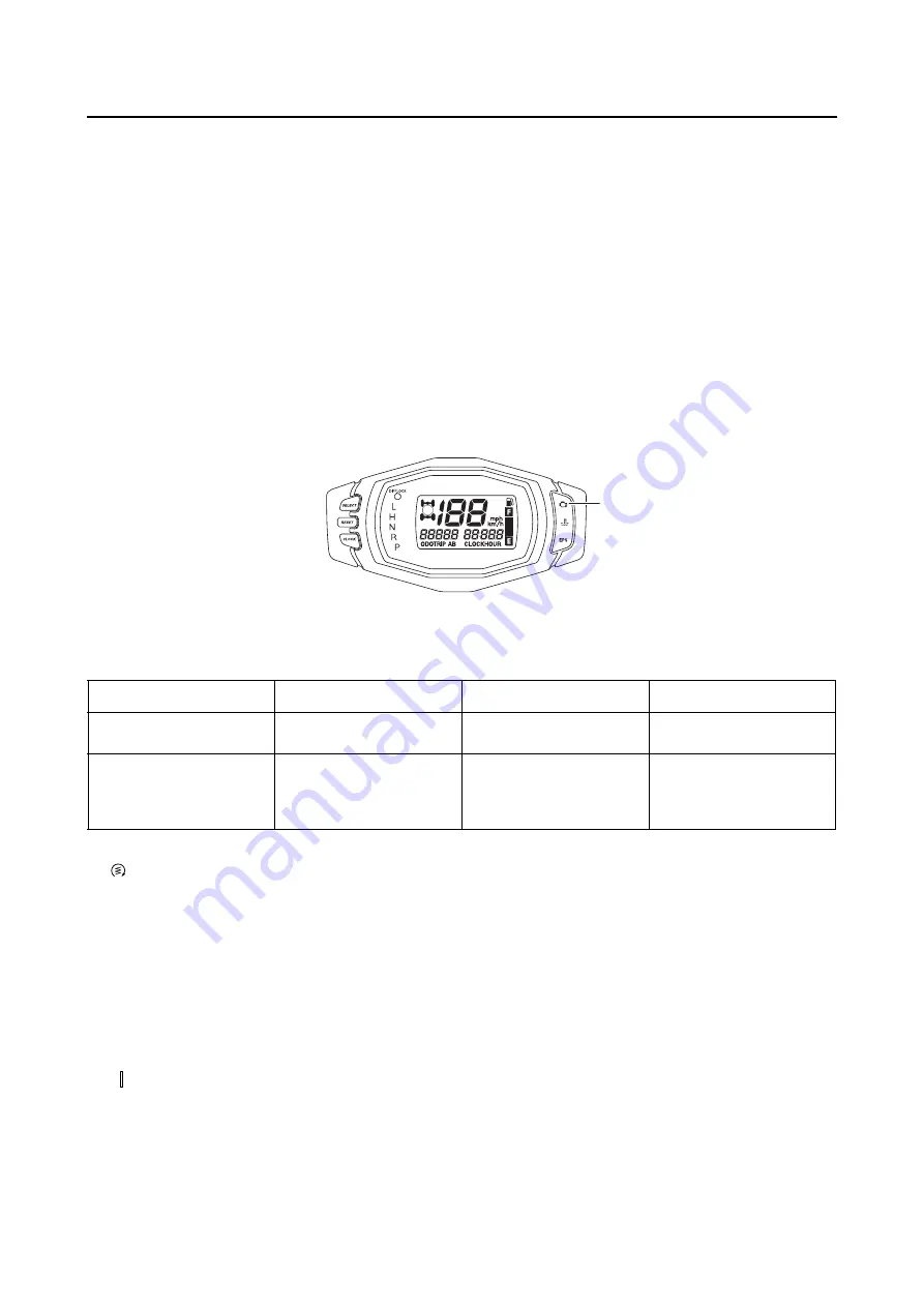
1
1. Engine trouble warning light
Warning light indication
ECU operation
FI operation
Vehicle operation
Flashing*
Warning provided when
unable to start engine
Operation stopped
Cannot be operated
Remains on
Malfunction detected
Operated with substitute
characteristics in accor-
dance with the descrip-
tion of the malfunction
Can or cannot be operat-
ed depending on the fault
code
12:
Crankshaft position sensor
39:
Fuel injector
(open or short-circuit)
30:
Lean angle sensor
(latch up detected)
41:
Lean angle sensor
(open or short-circuit)
33:
Faulty ignition
50:
ECU internal malfunction
(faulty ECU memory)
Содержание 2016 Grizzly yf700gg
Страница 6: ......
Страница 8: ......
Страница 11: ...IDENTIFICATION 1 2 ...
Страница 37: ...ENGINE SPECIFICATIONS 2 6 Air induction system Solenoid resistance 18 22 Ω ...
Страница 58: ...LUBRICATION SYSTEM CHART AND DIAGRAMS 2 27 EBS30023 LUBRICATION DIAGRAMS 6 7 8 9 3 4 3 2 1 5 ...
Страница 60: ...LUBRICATION SYSTEM CHART AND DIAGRAMS 2 29 1 2 3 4 5 ...
Страница 62: ...COOLING SYSTEM DIAGRAMS 2 31 EBS20021 COOLING SYSTEM DIAGRAMS 1 2 3 10 9 8 6 7 5 4 ...
Страница 72: ...CABLE ROUTING 2 41 Engine right side view 2 C E 1 9 10 E 1 9 10 E 5 6 9 A B C D 1 2 3 4 5 6 7 8 ...
Страница 76: ...CABLE ROUTING 2 45 Engine top view B 5 6 7 8 9 10 11 12 13 14 15 16 17 A 1 2 3 4 19 20 21 22 C 18 11 17 17 ...
Страница 78: ...CABLE ROUTING 2 47 Front and rear brake hoses F 3 F 3 F 3 3 I G H 4 4 B C D 2 E D 2 A 1 ...
Страница 80: ...CABLE ROUTING 2 49 ...
Страница 83: ......
Страница 119: ...PERIODIC MAINTENANCE 3 36 A Headlight left and right B Handle mounted light b a 1 A b a 1 B ...
Страница 120: ...PERIODIC MAINTENANCE 3 37 ...
Страница 183: ...STEERING STEM 4 60 TIP Align the punch mark a on the EPS unit with the groove b in the pitman arm 1 b a ...
Страница 197: ...REAR ARMS AND REAR SHOCK ABSORBER ASSEMBLIES 4 74 7 9 8 9 7 3 5 4 5 3 6 2 10 10 1 ...
Страница 198: ...REAR ARMS AND REAR SHOCK ABSORBER ASSEMBLIES 4 75 ...
Страница 203: ...ENGINE INSPECTION 5 2 Top cover Refer to GENERAL CHASSIS 2 on page 4 6 ...
Страница 244: ...ELECTRIC STARTER 5 43 a b b 1 2 3 ...
Страница 316: ...AIR INDUCTION SYSTEM 7 9 EBS20057 AIR INDUCTION SYSTEM 3 4 1 2 3 4 1 2 ...
Страница 352: ...REAR CONSTANT VELOCITY SHAFT ASSEMBLIES FINAL DRIVE ASSEMBLY AND REAR DRIVE SHAFT 8 31 ...
Страница 355: ......
Страница 365: ...ELECTRIC STARTING SYSTEM 9 10 ...
Страница 369: ...CHARGING SYSTEM 9 14 ...
Страница 417: ...FUEL PUMP SYSTEM 9 62 ...
Страница 432: ...ELECTRICAL COMPONENTS 9 77 EBS20084 ELECTRICAL COMPONENTS 4 5 6 7 8 9 10 11 12 13 14 15 16 17 19 18 1 2 3 ...
Страница 434: ...ELECTRICAL COMPONENTS 9 79 1 2 3 5 7 8 9 10 11 12 13 14 15 16 17 18 19 4 6 ...
Страница 454: ...ELECTRICAL COMPONENTS 9 99 ...
Страница 461: ...TROUBLESHOOTING 10 6 Too many electrical accessories Incorrect connection Faulty tail brake light assembly ...
Страница 468: ......
Страница 469: ......
Страница 470: ......