


MIDDLE GEAR
5-90
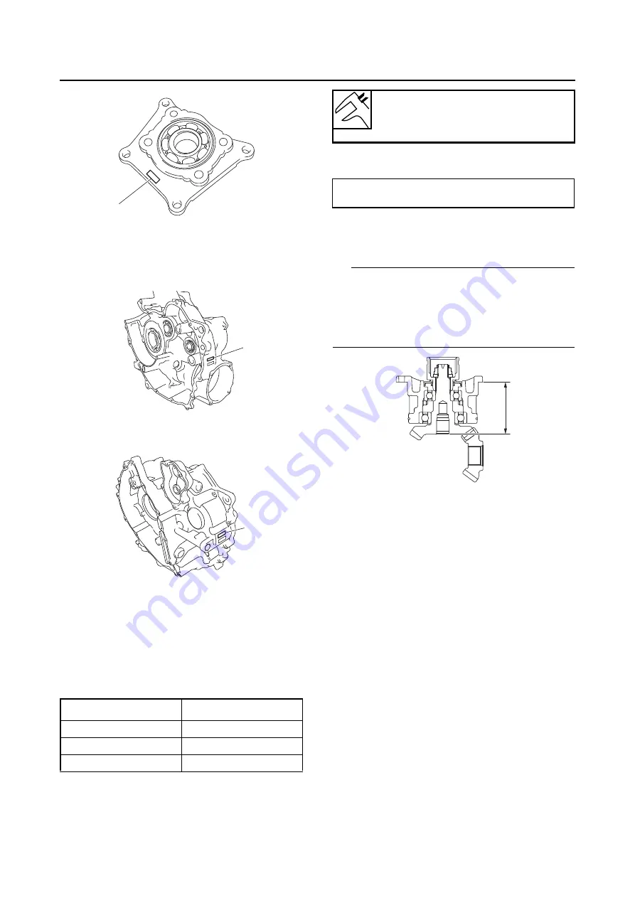
“b” is 17.0
“c” is 55.0
If the crankcase (right) is marked “64.96”,
“d” is 64.96
If the crankcase (left) is marked “9.01”,
“e” is 9.01
Therefore, “A” is 1.39.
“A” = 9.01 + 64.96 - 17.0 - 55.0 - 0.58
= 1.39
Round off hundredths digit and select appro-
priate shim(s).
In the above example, the calculated shim
thickness is 1.39 mm. The following chart in-
structs you, however, to round off 9 to 10.
Shims are supplied in the following thickness-
es.
c. To find middle driven pinion gear shim thick-
ness “B”, use the following formula.
“f” = a numeral (usually a decimal number) on
the bearing housing is either added to or sub-
tracted from “77.5”
TIP
After replacing any part in the middle driven pin-
ion gear assembly, the overall length of the as-
sembly will change. Therefore, be sure to
measure distance “f” to select the correct middle
driven pinion gear shim thickness.
“g” = a numeral (usually a decimal number)
on the middle driven pinion gear is either add-
ed to or subtracted from “49.0”
“h” = a numeral (usually a decimal number)
on the middle driven pinion gear is either add-
ed to or subtracted from “80.5”
“i” = a numeral (usually a decimal number) on
the left crankcase specifies a thickness of
“99.98”
“j” = a numeral (usually a decimal number) on
the right crankcase specifies a thickness of
“8.12”
Example:
If the bearing housing is marked “+03”,
“f” is 77.53
Hundredth
Rounded value
0, 1, 2
0
3, 4, 5, 6, 7
5
8, 9
10
a
d
e
Middle drive pinion gear shim
Thickness (mm)
0.50 0.55 0.60 0.70 0.80 0.90 1.00
Middle driven pinion gear shim thickness
“B” = “f” - “g” + “h” - “i” - “j”
f
Содержание 2016 Grizzly yf700gg
Страница 6: ......
Страница 8: ......
Страница 11: ...IDENTIFICATION 1 2 ...
Страница 37: ...ENGINE SPECIFICATIONS 2 6 Air induction system Solenoid resistance 18 22 Ω ...
Страница 58: ...LUBRICATION SYSTEM CHART AND DIAGRAMS 2 27 EBS30023 LUBRICATION DIAGRAMS 6 7 8 9 3 4 3 2 1 5 ...
Страница 60: ...LUBRICATION SYSTEM CHART AND DIAGRAMS 2 29 1 2 3 4 5 ...
Страница 62: ...COOLING SYSTEM DIAGRAMS 2 31 EBS20021 COOLING SYSTEM DIAGRAMS 1 2 3 10 9 8 6 7 5 4 ...
Страница 72: ...CABLE ROUTING 2 41 Engine right side view 2 C E 1 9 10 E 1 9 10 E 5 6 9 A B C D 1 2 3 4 5 6 7 8 ...
Страница 76: ...CABLE ROUTING 2 45 Engine top view B 5 6 7 8 9 10 11 12 13 14 15 16 17 A 1 2 3 4 19 20 21 22 C 18 11 17 17 ...
Страница 78: ...CABLE ROUTING 2 47 Front and rear brake hoses F 3 F 3 F 3 3 I G H 4 4 B C D 2 E D 2 A 1 ...
Страница 80: ...CABLE ROUTING 2 49 ...
Страница 83: ......
Страница 119: ...PERIODIC MAINTENANCE 3 36 A Headlight left and right B Handle mounted light b a 1 A b a 1 B ...
Страница 120: ...PERIODIC MAINTENANCE 3 37 ...
Страница 183: ...STEERING STEM 4 60 TIP Align the punch mark a on the EPS unit with the groove b in the pitman arm 1 b a ...
Страница 197: ...REAR ARMS AND REAR SHOCK ABSORBER ASSEMBLIES 4 74 7 9 8 9 7 3 5 4 5 3 6 2 10 10 1 ...
Страница 198: ...REAR ARMS AND REAR SHOCK ABSORBER ASSEMBLIES 4 75 ...
Страница 203: ...ENGINE INSPECTION 5 2 Top cover Refer to GENERAL CHASSIS 2 on page 4 6 ...
Страница 244: ...ELECTRIC STARTER 5 43 a b b 1 2 3 ...
Страница 316: ...AIR INDUCTION SYSTEM 7 9 EBS20057 AIR INDUCTION SYSTEM 3 4 1 2 3 4 1 2 ...
Страница 352: ...REAR CONSTANT VELOCITY SHAFT ASSEMBLIES FINAL DRIVE ASSEMBLY AND REAR DRIVE SHAFT 8 31 ...
Страница 355: ......
Страница 365: ...ELECTRIC STARTING SYSTEM 9 10 ...
Страница 369: ...CHARGING SYSTEM 9 14 ...
Страница 417: ...FUEL PUMP SYSTEM 9 62 ...
Страница 432: ...ELECTRICAL COMPONENTS 9 77 EBS20084 ELECTRICAL COMPONENTS 4 5 6 7 8 9 10 11 12 13 14 15 16 17 19 18 1 2 3 ...
Страница 434: ...ELECTRICAL COMPONENTS 9 79 1 2 3 5 7 8 9 10 11 12 13 14 15 16 17 18 19 4 6 ...
Страница 454: ...ELECTRICAL COMPONENTS 9 99 ...
Страница 461: ...TROUBLESHOOTING 10 6 Too many electrical accessories Incorrect connection Faulty tail brake light assembly ...
Страница 468: ......
Страница 469: ......
Страница 470: ......