


FUEL INJECTION SYSTEM
9-32
When an abnormal signal is received from a sensor, the ECU processes the specified values that are
programmed for each sensor in order to provide the engine with alternate operating instructions that
enable the engine to continue to operate or stop operating, depending on the conditions.
EBS30279
TROUBLESHOOTING METHOD
The engine operation is not normal and the engine trouble warning light comes on.
1. Check:
• Fault code number
▼▼▼
▼
▼ ▼▼▼
▼
▼ ▼▼▼
▼
▼ ▼▼▼
▼
▼ ▼▼▼
▼
▼ ▼▼▼
▼
▼▼▼ ▼▼▼
▼
▼ ▼▼▼
▼
▼ ▼▼▼
▼
▼ ▼▼▼
▼
▼ ▼▼▼
▼
▼ ▼▼▼
▼
▼▼▼▼ ▼▼
▼
a. Check the fault code number displayed on the meter or Yamaha diagnostic tool.
b. Identify the faulty system with the fault code.
c. Identify the probable cause of the malfunction.
▲▲▲
▲
▲ ▲▲▲
▲
▲ ▲▲▲
▲
▲ ▲▲▲
▲
▲ ▲▲▲
▲
▲ ▲▲▲
▲
▲▲▲ ▲▲▲
▲
▲ ▲▲▲
▲
▲ ▲▲▲
▲
▲ ▲▲▲
▲
▲ ▲▲▲
▲
▲ ▲▲▲
▲
▲▲▲ ▲▲▲
▲
2. Check and repair the probable cause of malfunction.
3. Perform the reinstatement action for the fuel injection system.
Refer to “Confirmation of service completion” of table in “TROUBLESHOOTING DETAILS (FUEL
INJECTION SYSTEM)” on page 9-35.
4. Turn the main switch to “
” (off) and back to “
” (on), then check that no fault code number is dis-
played.
TIP
If another fault code are displayed, repeat steps (1) to (4) until no fault code number is displayed.
5. Erase the malfunction history in the diagnostic mode (code No. 62). Refer to “SELF-DIAGNOSTIC
FUNCTION AND DIAGNOSTIC CODE TABLE” on page 10-7.
TIP
Turning the main switch to “
” (off) will not erase the malfunction history.
The engine operation is not normal, but the engine trouble warning light does not come on.
1. Check the operation of the following sensors and actuators in the diagnostic mode.
Refer to “TROUBLESHOOTING DETAILS (FUEL INJECTION SYSTEM)” on page 9-35 and “SELF-
DIAGNOSTIC FUNCTION AND DIAGNOSTIC CODE TABLE” on page 10-7.
If a malfunction is detected in the sensors or actuators, repair or replace all faulty parts.
If no malfunction is detected in the sensors and actuators, check and repair inner parts of the engine.
EBS30280
YAMAHA DIAGNOSTIC TOOL
This model uses the Yamaha diagnostic tool to identify malfunctions.
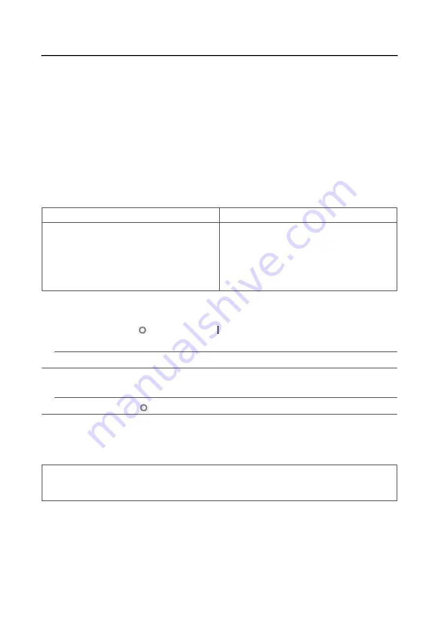
Fault code No.
No fault code No.
Check and repair. Refer to “TROUBLESHOOTING
DETAILS (FUEL INJECTION SYSTEM)” on page
9-35.
Monitor the operation of the sensors and actuators in
the diagnostic mode. Refer to “TROUBLESHOOT-
ING DETAILS (FUEL INJECTION SYSTEM)” on
page 9-35 and “SELF-DIAGNOSTIC FUNCTION
AND DIAGNOSTIC CODE TABLE” on page 10-7.
Check and repair.
01: Throttle position sensor signal (throttle angle)
30: Ignition coil
36: Fuel injector
48: Air induction system solenoid
Содержание 2016 Grizzly yf700gg
Страница 6: ......
Страница 8: ......
Страница 11: ...IDENTIFICATION 1 2 ...
Страница 37: ...ENGINE SPECIFICATIONS 2 6 Air induction system Solenoid resistance 18 22 Ω ...
Страница 58: ...LUBRICATION SYSTEM CHART AND DIAGRAMS 2 27 EBS30023 LUBRICATION DIAGRAMS 6 7 8 9 3 4 3 2 1 5 ...
Страница 60: ...LUBRICATION SYSTEM CHART AND DIAGRAMS 2 29 1 2 3 4 5 ...
Страница 62: ...COOLING SYSTEM DIAGRAMS 2 31 EBS20021 COOLING SYSTEM DIAGRAMS 1 2 3 10 9 8 6 7 5 4 ...
Страница 72: ...CABLE ROUTING 2 41 Engine right side view 2 C E 1 9 10 E 1 9 10 E 5 6 9 A B C D 1 2 3 4 5 6 7 8 ...
Страница 76: ...CABLE ROUTING 2 45 Engine top view B 5 6 7 8 9 10 11 12 13 14 15 16 17 A 1 2 3 4 19 20 21 22 C 18 11 17 17 ...
Страница 78: ...CABLE ROUTING 2 47 Front and rear brake hoses F 3 F 3 F 3 3 I G H 4 4 B C D 2 E D 2 A 1 ...
Страница 80: ...CABLE ROUTING 2 49 ...
Страница 83: ......
Страница 119: ...PERIODIC MAINTENANCE 3 36 A Headlight left and right B Handle mounted light b a 1 A b a 1 B ...
Страница 120: ...PERIODIC MAINTENANCE 3 37 ...
Страница 183: ...STEERING STEM 4 60 TIP Align the punch mark a on the EPS unit with the groove b in the pitman arm 1 b a ...
Страница 197: ...REAR ARMS AND REAR SHOCK ABSORBER ASSEMBLIES 4 74 7 9 8 9 7 3 5 4 5 3 6 2 10 10 1 ...
Страница 198: ...REAR ARMS AND REAR SHOCK ABSORBER ASSEMBLIES 4 75 ...
Страница 203: ...ENGINE INSPECTION 5 2 Top cover Refer to GENERAL CHASSIS 2 on page 4 6 ...
Страница 244: ...ELECTRIC STARTER 5 43 a b b 1 2 3 ...
Страница 316: ...AIR INDUCTION SYSTEM 7 9 EBS20057 AIR INDUCTION SYSTEM 3 4 1 2 3 4 1 2 ...
Страница 352: ...REAR CONSTANT VELOCITY SHAFT ASSEMBLIES FINAL DRIVE ASSEMBLY AND REAR DRIVE SHAFT 8 31 ...
Страница 355: ......
Страница 365: ...ELECTRIC STARTING SYSTEM 9 10 ...
Страница 369: ...CHARGING SYSTEM 9 14 ...
Страница 417: ...FUEL PUMP SYSTEM 9 62 ...
Страница 432: ...ELECTRICAL COMPONENTS 9 77 EBS20084 ELECTRICAL COMPONENTS 4 5 6 7 8 9 10 11 12 13 14 15 16 17 19 18 1 2 3 ...
Страница 434: ...ELECTRICAL COMPONENTS 9 79 1 2 3 5 7 8 9 10 11 12 13 14 15 16 17 18 19 4 6 ...
Страница 454: ...ELECTRICAL COMPONENTS 9 99 ...
Страница 461: ...TROUBLESHOOTING 10 6 Too many electrical accessories Incorrect connection Faulty tail brake light assembly ...
Страница 468: ......
Страница 469: ......
Страница 470: ......